Thermoelectric unit thermoelectric decoupling system and operation method

A thermoelectric unit and thermoelectric technology, which is applied in heating systems, hot water central heating systems, heating methods, etc., can solve problems such as low energy utilization efficiency and inability to meet power grid electricity requirements, and achieve improved heating efficiency and flexibility. to achieve the effect of thermo-electrolysis coupling

Active Publication Date: 2021-03-12
ELECTRIC POWER RESEARCH INSTITUTE OF STATE GRID SHANDONG ELECTRIC POWER COMPANY +2
View PDF9 Cites 1 Cited by
  • Summary
  • Abstract
  • Description
  • Claims
  • Application Information

AI Technical Summary

Problems solved by technology

[0004] Thermal power units refer to thermal power units that are connected to the grid for power generation and heat supply. With the acceleration of urbanization, the urban heating area continues to increase, and the heat load demand is increasing. According to the current "heat-based power" model, priority is given to Residential heat supply cannot meet the power requirements of the grid. This requires thermoelectric decoupling of the thermoelectric unit to improve the flexibility of the thermoelectric unit, that is, to maximize the power supply capacity under the premise of meeting the heat supply
[0005] At present, conventional thermoelectric decoupling includes low-pressure cylinder removal technology, high back pressure technology, heat storage tank, main steam bypass heating technology, etc., but there is a drawback in all of them, that is, using high-quality steam or electric heat to increase the heating capacity. Water, the overall energy utilization efficiency of the unit is low

Method used


Image

  • Thermoelectric unit thermoelectric decoupling system and operation method

Examples


Embodiment 1

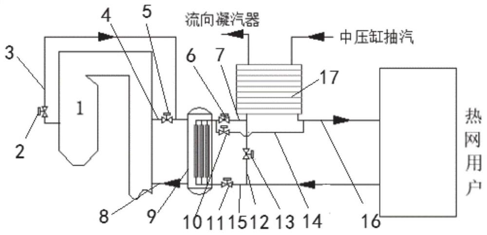
[0034] In this embodiment, a thermoelectric decoupling system of a thermoelectric unit is disclosed, with a structure such as figure 1 As shown, it includes a furnace 1, a heat exchange boiler 9 and a thermal station 17. The air inlet of the heat exchange boiler 1 communicates with the first pipe 3 and the second pipe 4 respectively, and the first pipe 3 communicates with the high-temperature flue gas outlet of the furnace 1. The second pipeline 4 communicates with the low-temperature flue gas outlet of the furnace 1, and the high-temperature flue gas and low-temperature flue gas of the furnace 1 are mixed into medium-temperature flue gas and then enter the heat exchange boiler 9 to release heat, which is the heat exchange boiler 9 The water is heated, and the high-temperature flue gas outlet baffle 2 is set on the first pipe 3, and the low-temperature flue gas outlet baffle 5 is set on the second pipe 4. By adjusting the high-temperature flue gas outlet baffle 2 and the low-te...

Embodiment 2

[0050] In this embodiment, a method for operating a thermoelectric decoupling system of a thermoelectric unit is proposed, including:

[0051] When the heating and power supply are all satisfied, the seventh valve is opened, the third valve, the fourth valve, and the sixth valve are closed, and the high-temperature water required by the heating network users is completely provided by the thermal station, and the low-temperature water discharged by the heating network users is re- Enter the thermal station to absorb heat.

[0052] In this case, in order to prevent the heat exchange boiler from being damaged due to dry burning, the high-temperature flue gas outlet baffle and the low-temperature flue gas outlet baffle are closed at the same time.

[0053] When the heat supply is satisfied and the power supply is not satisfied, the fourth valve and the sixth valve are opened, the third valve and the seventh valve are closed, and the high-temperature water of the heat exchange boil...


PUM


Abstract

The invention discloses a thermoelectric unit thermoelectric decoupling system and an operation method. The system comprises a hearth, a heat exchange boiler and a heating station. A water outlet of the heat exchange boiler communicates with a third pipeline and a fourth pipeline, the third pipeline communicates with a water inlet of the heating station, and a water outlet of the heating station communicates with a fifth pipeline. The fifth pipeline is used for communicating with a circulating water inlet of a heat supply network user, the fourth pipeline communicates with the fifth pipeline,the water inlet of the heating station further communicates with a seventh pipeline, the seventh pipeline is used for communicating with a circulating water outlet of the heat supply network user, a water inlet of the heat exchange boiler communicates with a sixth pipeline, the sixth pipeline communicates with the seventh pipeline, a third valve is arranged on the third pipeline, a fourth valve isarranged on the fourth pipeline, a sixth valve is arranged on the sixth pipeline, and a seventh valve is arranged on the seventh pipeline. Thermoelectric decoupling of a thermoelectric unit is realized, and flexibility of the thermoelectric unit is improved.

Description

technical field [0001] The invention relates to the technical field of cogeneration of heat and power, in particular to a thermoelectric decoupling system and an operation method of a thermoelectric unit. Background technique [0002] The statements in this section merely provide background information related to the present disclosure and do not necessarily constitute prior art. [0003] As a large number of new energy sources are connected to the grid, and the proportion of foreign power and nuclear power is increasing, the deep peak regulation of thermal power plants has become a trend and is becoming more and more frequent. [0004] Thermal power units refer to thermal power units that are connected to the grid for power generation and heat supply. With the acceleration of urbanization, the urban heating area continues to increase, and the heat load demand is increasing. According to the current "heat-based power" model, priority is given to Residential heat supply cann...

Claims


Application Information

Patent Timeline
Patent Type & Authority Applications(China)
IPC IPC(8): F24D3/02F24D19/10
CPCF24D3/02F24D19/1015
Inventor 崔福兴游大宁张绪辉庞向坤王海超刘景龙刘科张利孟赵中华
Owner ELECTRIC POWER RESEARCH INSTITUTE OF STATE GRID SHANDONG ELECTRIC POWER COMPANY
Why Eureka
Try Eureka