High-temperature vacuum sintering furnace lifting frame device

A high-temperature vacuum and sintering furnace technology, which is applied in the direction of furnace safety devices, furnaces, muffle furnaces, etc., can solve the problems of easy damage, no protective measures, etc., and achieve the effect of avoiding movement and dislocation

Inactive Publication Date: 2021-03-12
江西省晶为光电科技有限公司
View PDF0 Cites 5 Cited by
  • Summary
  • Abstract
  • Description
  • Claims
  • Application Information

AI Technical Summary

Problems solved by technology

[0003] In order to enable people to use the vacuum sintering furnace safely, the vacuum sintering furnace can be lifted and protected, so as to avoid harming the user. Now there is no protective measure when using it, and it is easy to hurt people themselves. Therefore, a A high-temperature vacuum sintering furnace lifter device that can achieve high safety and is easy to use

Method used


Image

  • High-temperature vacuum sintering furnace lifting frame device
  • High-temperature vacuum sintering furnace lifting frame device
  • High-temperature vacuum sintering furnace lifting frame device

Examples


Embodiment 1

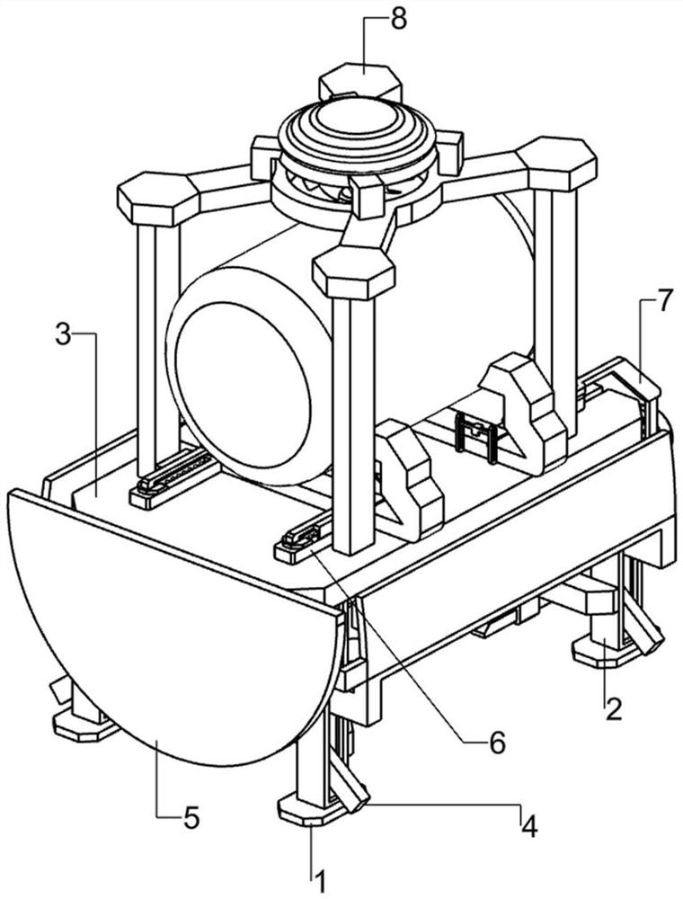
[0058] A high-temperature vacuum sintering furnace lifting frame device, such as Figure 1-3 As shown, it includes a bottom plate 1, a support frame 2, a placement component 3 and a lifting mechanism 4. The bottom plate 1 is provided with a support frame 2, and a placement component 3 is connected between the support frames 2, and a lifting mechanism 4 is provided on the placement component 3. .

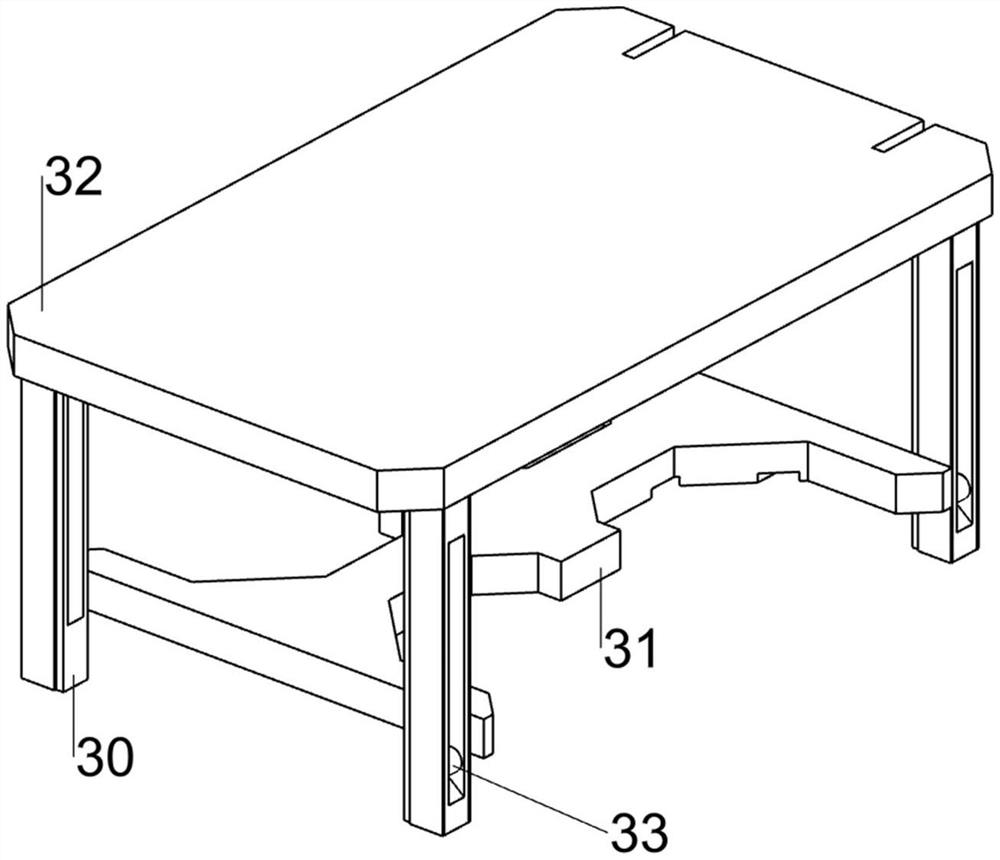
[0059] The placement assembly 3 includes a mounting plate 30, a connecting plate 31, a lifting plate 32 and a fixed rod 33. The mounting plate 30 is slidably connected in the support frame 2, and the lifting plate 32 is connected between the tops of the mounting plate 30. Connecting plates 31 are connected between them, and fixing rods 33 are arranged in the mounting plates 30 .

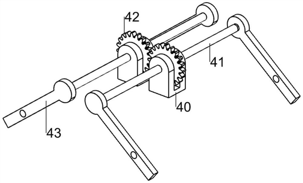
[0060] Lifting mechanism 4 comprises bearing seat 40, rotating shaft 41, gear 42 and crank 43, and connecting plate 31 top front and rear sides are all connected with bearing seat 40, and the bearing seat ...

Embodiment 2

[0063] On the basis of Example 1, such as Figure 4-8 As shown, a baffle 5 is also included, and the baffle 5 includes a rising block 50, a side protection plate 51 and a front protection plate 52, and a rising block 50 is arranged between the horizontal mounting plates 30, and a rising block 50 is provided on the top of the rising block 50. There are side shields 51, and a front shield 52 is connected between the left sides of the side shields 51.

[0064] The upward movement of the mounting plate 30 drives the rising block 50, the side protection plate 51 and the front portion protection plate 52 to move upwards, which plays a protective role for people, and the downward movement of the mounting plate 30 drives the rising block 50, the side protection plate 51 and the front portion protection plate 52 Move down to reset.

[0065]Also includes clamping mechanism 6, clamping mechanism 6 includes first slide rail 60, first spring 61, hook slider 62, anti-skid clamp 63, second ...


PUM


Abstract

The invention relates to a lifting frame device, in particular to a high-temperature vacuum sintering furnace lifting frame device. The high-temperature vacuum sintering furnace lifting frame device is high in safety and simple to use. According to the technical scheme, the high-temperature vacuum sintering furnace lifting frame device comprises a bottom plate and supporting frames, a placing assembly and a lifting mechanism, wherein the supporting frames are arranged on the bottom plate at equal intervals; the placing assembly is connected between the supporting frames; and the lifting mechanism is arranged on the placing assembly. Through cooperation of the placing assembly and the lifting mechanism, a vacuum sintering furnace can move up and down, and therefore people can use the vacuumsintering furnace conveniently.

Description

technical field [0001] The invention relates to a lifting frame device, in particular to a lifting frame device for a high-temperature vacuum sintering furnace. Background technique [0002] Vacuum sintering furnace refers to a furnace for protective sintering of heated items in a vacuum environment. There are many heating methods, such as resistance heating, induction heating, microwave heating, etc. Vacuum sintering furnace uses induction heating to protect heated items The sintering furnace can be divided into power frequency, intermediate frequency, high frequency and other types, which can be classified as a sub-category of vacuum sintering furnace. The tungsten crucible in the coil generates high temperature, so people should pay special attention during use. [0003] In order to enable people to use the vacuum sintering furnace safely, the vacuum sintering furnace can be lifted and protected, so as to avoid harming the user. Now there are no protective measures when ...

Claims


Application Information

Patent Timeline
Patent Type & Authority Applications(China)
IPC IPC(8): F27B5/05F27B5/06F27D21/00
CPCF27B5/04F27B5/06F27D21/00F27D2021/0057
Inventor 吴磊
Owner 江西省晶为光电科技有限公司
Why Eureka
Try Eureka