Check patentability & draft patents in minutes with Patsnap Eureka AI!

Interferometer displacement measurement system and method

A displacement measurement and interferometer technology, applied in measurement devices, instruments, optical devices, etc., can solve the problems of poor detection quality, small application range, low accuracy, etc., to reduce the influence, eliminate the influence of fringe contrast, The effect of compensating for air disturbance errors

Active Publication Date: 2021-03-12
BEIJING U PRECISION TECH +1
View PDF24 Cites 5 Cited by
  • Summary
  • Abstract
  • Description
  • Claims
  • Application Information

AI Technical Summary

Problems solved by technology

[0005] In view of the above problems, the object of the present invention is to provide an interferometer displacement measurement system and method to solve the problems of the current interferometers such as large volume, poor detection quality, low accuracy, and small application range.

Method used


Image

  • Interferometer displacement measurement system and method
  • Interferometer displacement measurement system and method
  • Interferometer displacement measurement system and method

Examples


Embodiment Construction

[0030] In the following description, for purposes of explanation, numerous specific details are set forth in order to provide a thorough understanding of one or more embodiments. It may be evident, however, that these embodiments may be practiced without these specific details. In other instances, well-known structures and devices are shown in block diagram form in order to facilitate describing one or more embodiments.

[0031] In order to describe the interferometer displacement measurement system and method of the present invention in detail, specific embodiments of the present invention will be described in detail below in conjunction with the accompanying drawings.

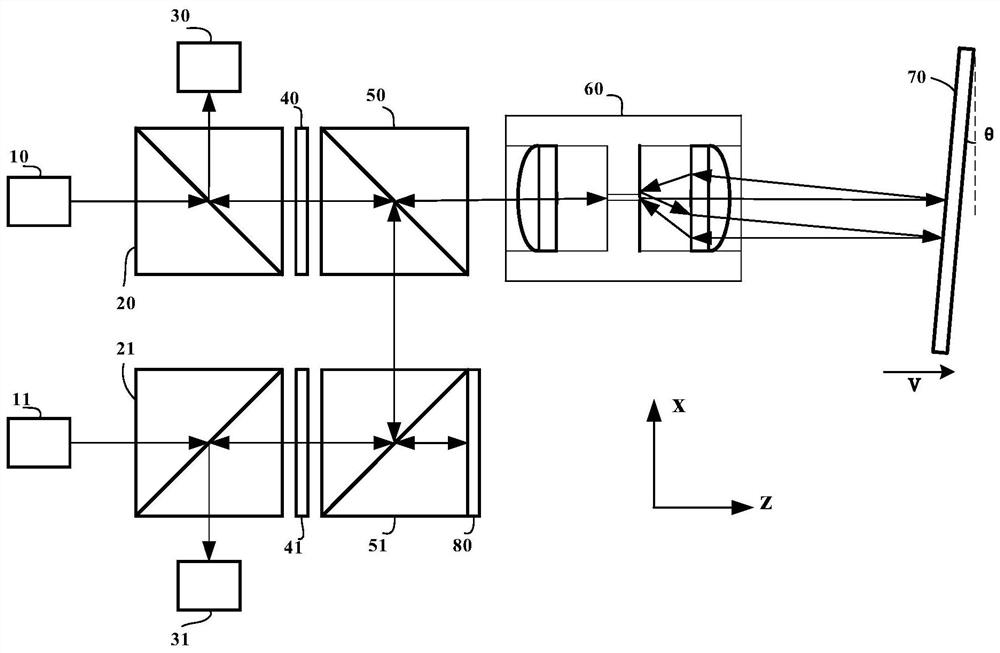
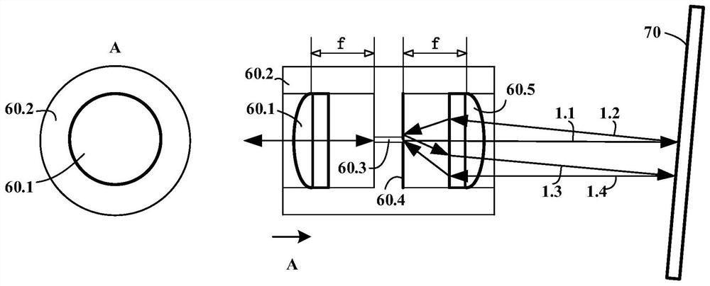
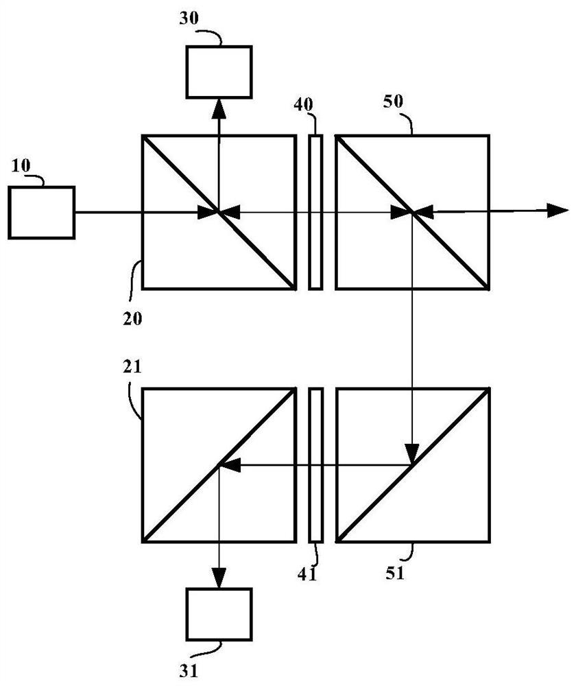
[0032] figure 1 A schematic structure of an interferometer displacement measurement system according to an embodiment of the present invention is shown.

[0033] Such as figure 1 As shown, the interferometer displacement measurement system of the embodiment of the present invention includes a first laser l...


PUM


Abstract

The invention provides an interferometer displacement measurement system and method. The system comprises the steps that: measurement light returns to a first photoelectric detector and a second photoelectric detector after being processed by a first polarization splitting prism, a first 1 / 4 wave plate, a first splitting prism, an optical waveguide assembly and a reflection device; reference lightreturns to the first photoelectric detector and the second photoelectric detector after being processed by a second polarization splitting prism, a second 1 / 4 wave plate, a second splitting prism anda reflector; the first photoelectric detector forms a measurement signal according to the processed measurement light and reference light, and the second photoelectric detector forms a reference signal according to the processed measurement light and reference light; and displacement information of a to-be-detected object is determined according to the measurement signal and the reference signal.With the system and method of the invention adopted, the displacement measurement error can be reduced, and the measurement precision and the measurement range are improved.

Description

technical field [0001] The invention relates to the technical field of precision displacement measurement, and more specifically, to an interferometer displacement measurement system and method. Background technique [0002] Precision measurement is the basis of precision processing, especially for IC equipment, nanometer or even sub-nanometer resolution has become the standard and requirement of precision measurement. At present, laser interferometer and grating interferometer are the research objects of precision measurement. requirements are also getting higher. [0003] However, in the actual displacement measurement process, due to the movement of the object and other factors, the grating or the mirror will produce a small rotation angle. Since there are stripes in the interference spot range, the photodetector is directly used to detect the interference spot, and the signal quality will be relatively poor. At present, the method to solve the problem of poor signal qua...

Claims


Application Information

Patent Timeline
Patent Type & Authority Applications(China)
IPC IPC(8): G01B11/02
CPCG01B11/02G01B2290/70G01B9/02007G01B9/02019G01B9/02001G01B9/02077G01B11/14
Inventor 孙国华高晓良徐蕾
Owner BEIJING U PRECISION TECH
Features
  • R&D
  • Intellectual Property
  • Life Sciences
  • Materials
  • Tech Scout
  • Unparalleled Data Quality
  • Higher Quality Content
  • 60% Fewer Hallucinations
Learn More