Mining machinery wheel shaft deflection measurement device

A measurement device and mechanical technology, applied in the field of deflection measurement, can solve the problems of low installation and fixation strength, limited scope of application, and only small-weight axles can be installed, so as to reduce the number of placements, increase the scope of application, and reduce costs input effect

Inactive Publication Date: 2021-03-12
德清凯晶光电科技有限公司
View PDF0 Cites 2 Cited by
  • Summary
  • Abstract
  • Description
  • Claims
  • Application Information

AI Technical Summary

Problems solved by technology

[0004] Aiming at the deficiencies of the prior art, the present invention provides a deflection measuring device for the wheel axle of mining machinery, which solves the problems of limited application range and low installation and fixing strength, and only small-weight axles can be installed

Method used


Image

  • Mining machinery wheel shaft deflection measurement device
  • Mining machinery wheel shaft deflection measurement device
  • Mining machinery wheel shaft deflection measurement device

Examples


Embodiment 1

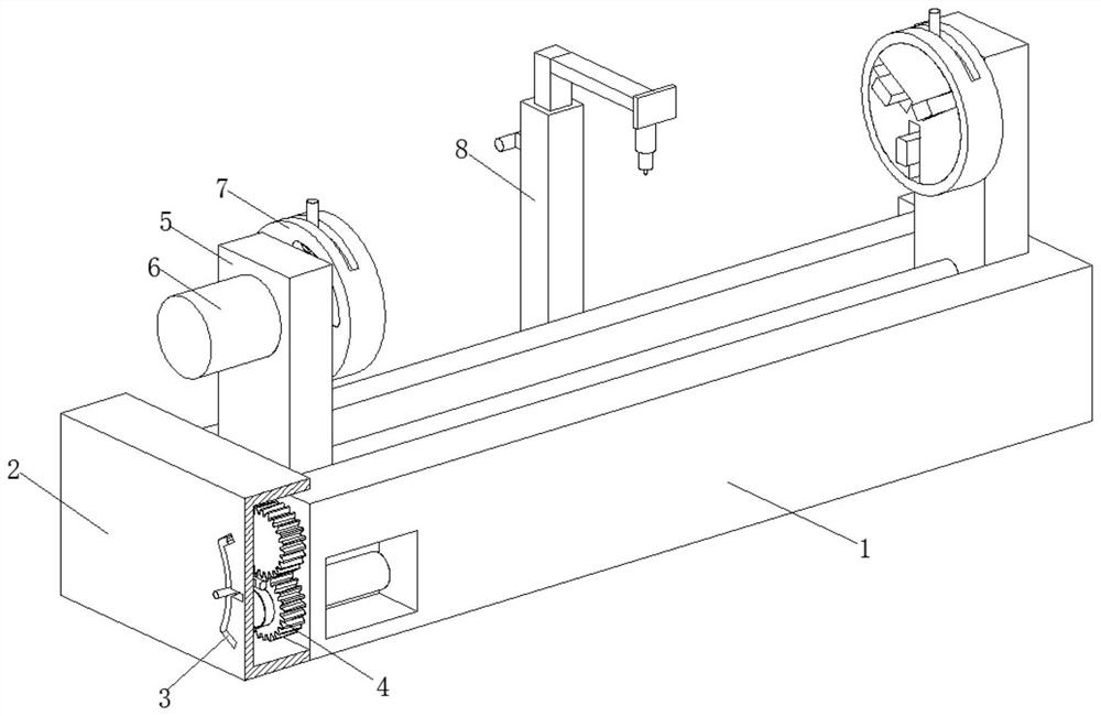
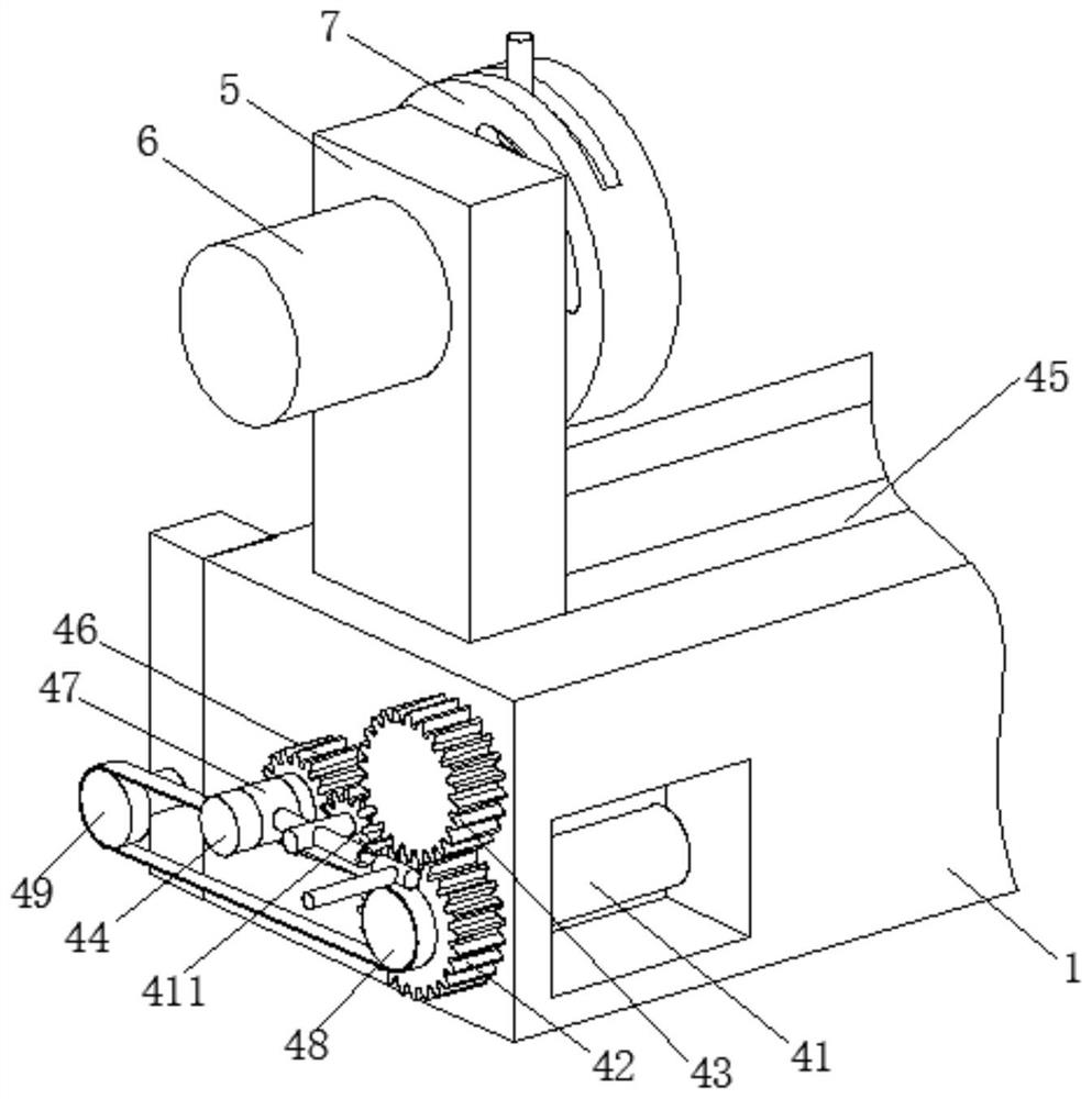
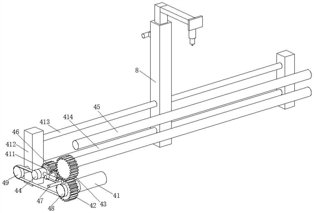
[0030] A deflection measuring device for a mining machinery wheel shaft, such as Figure 1-Figure 6 As shown, it includes a workbench 1, the front of the workbench 1 is connected with a protective box 2 by bolts, the front of the protective box 2 is provided with a card slot 3, the inside of the protective box 2 is provided with a transmission mechanism 4, and the inner wall of the workbench 1 Two support blocks 5 are slidingly connected, the front of the support block 5 is connected with a motor 6 by bolts, the rear of the support block 5 is provided with a clamping mechanism 7 , and the left side of the workbench 1 is provided with a detection mechanism 8 .

[0031] In this embodiment, the transmission mechanism 4 includes a motor 41, the output end of the motor 41 is clipped to a No. 1 gear 42, the surface of the No. 1 gear 42 is meshed with a No. 2 gear 43, and the inner wall of the workbench 1 is rotatably connected to a two-way screw 44; The inner wall of the workbench 1...

Embodiment 2

[0041] Such as Figure 6-Figure 7 As shown, on the basis of Embodiment 1, in this embodiment, the axis of the fixed disk 71 is clamped and fixed with the output end of the motor 6, the surface of the slider 76 is slidably connected with the inner wall of the limit disk 73, and the push rod The surface of 77 is movably connected with the inwall of fixed disk 71, and fixed disk 71 is provided with arc-shaped slide rail, and push rod 77 is slid on its inner wall, prevents because the inner wall of fixed disk 71 is threadedly connected with the surface of inner disk 72, causes straight line The slide rail of the push rod 77 is blocked, and then the inner disk 72 cannot be continued to rotate, so that the moving range of the slide block 76 is limited, and the axles with different diameters cannot be clamped, and the practicability is greatly reduced.

[0042] It is worth noting that the detection mechanism 8 includes a support column 81, the inner wall of the support column 81 is s...


PUM


Abstract

The invention relates to the technical field of deflection measurement, and discloses a mining machinery wheel shaft deflection measurement device which comprises a workbench, a protection box is connected to the front portion of the workbench through bolts, a clamping groove is formed in the front portion of the protection box, and a transmission mechanism is arranged in the protection box. Two supporting blocks are slidably connected to the inner wall of the workbench, motors are connected to the front portions of the supporting blocks through bolts, clamping mechanisms are arranged on the rear portions of the supporting blocks, and a detection mechanism is arranged on the left side of the workbench.Through cooperative use of the transmission mechanism and the supporting blocks, wheel shafts with different lengths can be clamped, so that the clamping mechanism can adapt to axles with different lengths, the application range of the clamping mechanism is widened, the axles can be clamped through the clamping mechanism, the clamping mechanism can adapt to the axles with different diameters and can be reinforced, the application range can be further widened, and the axles with largeweight can be clamped.

Description

technical field [0001] The invention relates to the technical field of yaw measurement, in particular to a yaw measurement device for a wheel shaft of a mining machine. Background technique [0002] When producing the axles of mining machinery, it is necessary to use the concentricity tester and yaw device to measure the concentricity and yaw of the produced axles in order to reduce the error. The concentricity tester is used for centrifugal pumps and compressors It is an ideal special measuring tool for two-axis concentricity finding of various rotating wheel shaft equipment such as fans, generators, etc. It has the characteristics of reasonable structure, high precision, small error, wide application range, and convenient use and maintenance. [0003] At present, the deflection measuring device of the wheel shaft on the market can only be applied to one type of wheel shaft, and cannot detect wheel shafts of different lengths and diameters, which limits the use of the measu...

Claims


Application Information

Patent Timeline
Patent Type & Authority Applications(China)
IPC IPC(8): G01B21/24G01B21/00
CPCG01B21/00G01B21/24
Inventor 沈斌斌
Owner 德清凯晶光电科技有限公司
Why Eureka
Try Eureka