Device and method for measuring optical path loss of optical fiber gyroscope

A technology for measuring optical fibers and gyroscopes, applied in the field of optical detection, can solve the problems that affect the measurement accuracy of fiber optic gyroscopes, cannot fully accurately measure the optical path loss of fiber optic gyroscopes, etc., so as to avoid insertion loss, high accuracy, and easy operation. Effect

Inactive Publication Date: 2021-03-12
XIAN SINO HUAXIN MEASUREMENT & CONTROL
View PDF8 Cites 0 Cited by
  • Summary
  • Abstract
  • Description
  • Claims
  • Application Information

AI Technical Summary

Problems solved by technology

[0003] At this stage, there are few methods for measuring the performance of the optical path. The main method is to use an optical power tester to measure the output optical power of the optical path at the end of the optical fiber to be fused with the detector before the optical path is assembled on the detector and the light source is working normally, and then query the optical power of the light source. α=-10lg(Pout / Pin) is used to calculate the optical path loss. This method does not include the insertion loss of the detector and the melting point loss of the coupler and the detector, and the performance of the detector and the quality of the fusion point greatly affect the optical fiber gyroscope. The measurement accuracy of the instrument, so the original method cannot completely and accurately measure the optical path loss of the entire fiber optic gyroscope

Method used


Image

  • Device and method for measuring optical path loss of optical fiber gyroscope
  • Device and method for measuring optical path loss of optical fiber gyroscope
  • Device and method for measuring optical path loss of optical fiber gyroscope

Examples


Embodiment Construction

[0027] The present invention is further described below in conjunction with accompanying drawing:

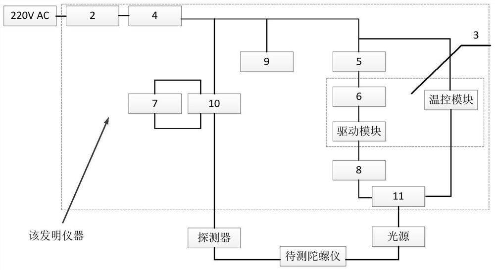
[0028] A device and method for measuring the optical path loss of a fiber optic gyroscope, as attached figure 1 As shown, the 220V AC power is converted into ±5V DC power supply through the transformer 2, one +5V power supply is supplied to the light source board 3 to provide the working conditions of the light source, one output ±5V power supply is used to ensure the normal operation of the detector, and one channel ±5V is used as the instrument’s power supply. The power supply of cooling fan 9 ensures that each device and chip can work in a suitable environment. Use digital display voltmeter 7 to test the voltage difference between detector 4 and 5 pins, and record the voltage values ​​before and after switch 5 is turned on. Denote it as Vn, and denote it as V after it is connected. The optical path loss of the fiber optic gyroscope can be obtained through calculation.

[002...


PUM


Abstract

The invention discloses a device for measuring optical path loss of an optical fiber gyroscope. The device comprises a case, a transformer, a light source plate, a digital display voltmeter and a digital display ammeter, the transformer, the light source plate, the digital display voltmeter and the digital display ammeter are arranged in the case; the IC locking seat and the connector socket are arranged on a side cover of the case; one end of the transformer is connected with an external power supply, and the other end of the transformer is divided into two paths, one path is connected with the IC locking seat, and the other path is sequentially connected with the light source plate, the digital ammeter and the connector socket; the digital display voltmeter is connected to the IC lockingseat in parallel; and the gyroscope to be tested is arranged outside the case. The measurement efficiency is much higher than that of a traditional optical path measurement method and is improved bymore than eight times; a light path is not touched, and introduction of human interference is avoided; and according to the invention, neglect of insertion loss in a traditional optical path measurement method is avoided, and the accuracy is higher.

Description

technical field [0001] The invention relates to the technical field of optical detection, in particular to a device and a measurement method for measuring the optical path loss of an optical fiber gyroscope. Background technique [0002] At present, the optical fiber gyroscope is produced after the optical path assembly is completed, and each optical component is easily affected by the manual assembly process and the external environment, thus affecting the performance of the entire optical fiber gyroscope. By measuring the optical path loss after the optical path assembly, it can be effectively Control the qualification rate of the entire fiber optic gyroscope optical path assembly. [0003] At this stage, there are few methods for measuring the performance of the optical path. The main method is to use an optical power tester to measure the output optical power of the optical path at the end of the optical fiber to be fused with the detector before the optical path is asse...

Claims


Application Information

Patent Timeline
Patent Type & Authority Applications(China)
IPC IPC(8): G01M11/00G01C25/00
CPCG01C25/00G01M11/33
Inventor 张斌訾吉朝管斌唐乾张户昌
Owner XIAN SINO HUAXIN MEASUREMENT & CONTROL
Why Eureka
Try Eureka