Miniature circuit breaker

A small circuit breaker, main body technology, applied in the direction of circuit, protection switch parts, electrical components, etc., can solve the problems of inconvenient disassembly and assembly of the shell, poor heat dissipation effect, etc., achieve stable and reliable placement, improve stability, and improve heat dissipation effect Effect

Pending Publication Date: 2021-03-12
BEIJING JINGSENYUAN ELECTRICAL APP CO LTD
View PDF15 Cites 3 Cited by
  • Summary
  • Abstract
  • Description
  • Claims
  • Application Information

AI Technical Summary

Problems solved by technology

[0004] In order to solve the technical problems of inconvenient disassembly and assembly of the miniature circuit breaker shell and poor heat dissipation effect in the prior art, the present invention provides a miniature circuit breaker

Method used


Image

  • Miniature circuit breaker
  • Miniature circuit breaker
  • Miniature circuit breaker

Examples


Embodiment 1

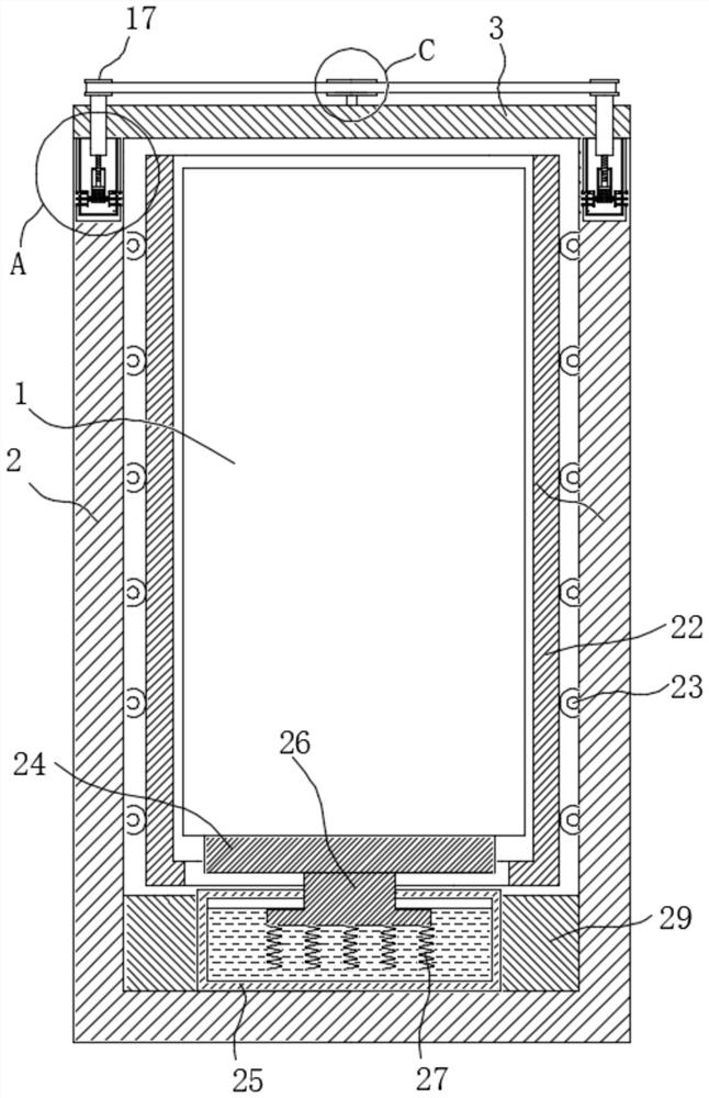
[0034] Please combine Figure 1 to Figure 4 , the miniature circuit breaker includes a miniature circuit breaker main body 1, the outer cover of the miniature circuit breaker main body 1 is provided with a housing 2, the outer cover of the miniature circuit breaker main body 1 is provided with a housing 2, and the housing 2 is reserved for the miniature circuit breaker The wire harness opening (not shown) through which the wire harness of the main body 1 passes. One end of the casing 2 has an insertion opening (not marked) for inserting the miniature circuit breaker main body 1 . A box body 25 is provided at the end of the casing 2 away from the insertion port, and the box body 25 contains a cooling liquid, which in this embodiment may be water or liquid freon. The side of the box body 25 facing the insertion opening is provided with a heat conduction assembly in contact with the main body 1 of the miniature circuit breaker. The heat conduction component is used to transfer ...

Embodiment 2

[0051] Please combine Figure 5 to Figure 7 , the present embodiment 2 is an improved solution of embodiment 1, specifically, a bead groove 1 34 is provided on the docking block 28, and a top bead 32 is connected to the bead groove 1 34 through a spring 2 33, and on the groove wall of the docking groove 30 Offer the top groove two 31 that cooperates with top ball two 32. Wherein when the deformation of the second spring 33 did not occur, the bead center of the top bead 2 32 was flush with the notch of the bead groove 1 34 .

[0052] In this embodiment, when the docking block 28 is just inserted into the docking groove 30 , the top ball 2 32 will be pressed into the bead groove 1 34 and the spring 2 33 will be compressed after receiving the pressing force from the wall of the docking groove 30 . And when the docking block 28 is fully inserted in the docking groove 30, the position of the top ball 2 32 corresponds to the position of the top groove 2 31, and the top ball 2 32 is...


PUM


Abstract

The invention relates to the technical field of circuit breakers, and discloses a miniature circuit breaker. The circuit breaker comprises a miniature circuit breaker main body, the outer side of theminiature circuit breaker main body is covered with a shell, and one end of the shell is provided with an insertion port. A box body is arranged at the end, away from the insertion opening, in the shell, and cooling liquid is contained in the box body. A heat conduction assembly is arranged on the side, facing the insertion opening, of the box. And a shell cover is arranged on the shell. A connecting block is arranged on the side, close to the shell, of the shell cover, a connecting groove is formed in the shell, and the connecting groove and the connecting block are locked and fixed through alocking mechanism. The miniature circuit breaker is accommodated in the space formed by the shell and the shell cover, a stable environment is provided for normal operation of the miniature circuit breaker, the shell and the shell cover are connected and fixed through the connecting groove and the connecting block, and the locking mechanism is additionally arranged on the basis, so the rapid disassembly and assembly between the shell and the shell cover are realized; the heat conduction assembly and the box body are additionally arranged in the shell, so that the heat dissipation effect is improved, and a stable temperature environment is provided for normal operation.

Description

technical field [0001] The invention relates to the technical field of circuit breakers, in particular to a small circuit breaker. Background technique [0002] Miniature circuit breakers, also known as miniature circuit breakers, are suitable for overload and short-circuit protection of AC 50 / 60Hz rated voltage 230 / 400V, rated current up to 63A, and can also be used for infrequent operation of the line under normal conditions. Miniature circuit breakers are mainly used in various places such as industry, commerce, high-rise buildings and residential buildings. [0003] When the existing miniature circuit breaker is used for a long time, its internal parts will be damaged by the influence of external environmental factors, and its service life is low. At present, the existing small circuit breakers with protective casings are fixed by a large number of screws, so when disassembling, the workload of workers will be greatly increased, which is very inconvenient. At the same t...

Claims


Application Information

Patent Timeline
Patent Type & Authority Applications(China)
IPC IPC(8): H01H71/02H01H9/52
CPCH01H71/0264H01H71/02H01H9/52
Inventor 崔高鹏黄凌志刘征黄立强
Owner BEIJING JINGSENYUAN ELECTRICAL APP CO LTD
Why Eureka
Try Eureka