
Atomization unit and atomization device

An atomization device and heating sheet technology, applied in the field of atomization, can solve the problems of dry burning of harmful substances, slow start of heat, uneven frame parts, etc., to achieve the effect of expanding the range of material selection, ensuring sufficient contact, and avoiding extrusion deformation

Pending Publication Date: 2021-03-16
SHENZHEN HUACHENGDA PRECISION IND CO LTD
View PDF0 Cites 4 Cited by
  • Summary
  • Abstract
  • Description
  • Claims
  • Application Information

AI Technical Summary

Problems solved by technology

[0005] 1. Due to the needs of the circuit and the heating area, the hollowing out forms a circuitous heating circuit, resulting in a relatively small connection point of the sheet heating body;
[0006] 2. For a larger heating area, the heating circuit is circuitous, causing the frame to be uneven and have no support
The product is weak, and it is easy to cause poor deformation during transportation and assembly, which is not conducive to mass production;
[0007] 3. Due to the insufficient support strength of the heating plate, it is difficult to ensure the fit with the fluid-conducting cotton. When the contact is not good, it is easy to cause local dry burning to produce harmful substances, which gives users a bad experience; in addition, the size and size of the product design and bad shape;
[0008] 4. The thickness of the heating sheet is limited by its strength and cannot be made thin, resulting in a large cross-sectional area of ​​the conductor when energized, and the problem of slow start-up of heat

Method used


Image

  • Atomization unit and atomization device
  • Atomization unit and atomization device
  • Atomization unit and atomization device

Examples


Embodiment Construction

[0039] In order to have a clearer understanding of the technical features, purposes and effects of the present invention, the specific implementation manners of the present invention will now be described in detail with reference to the accompanying drawings.

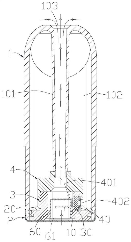
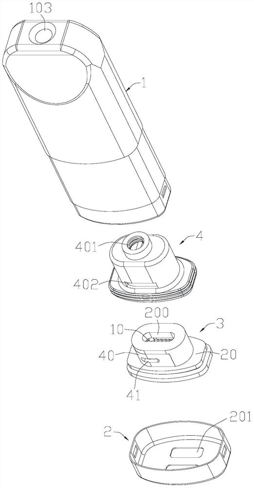
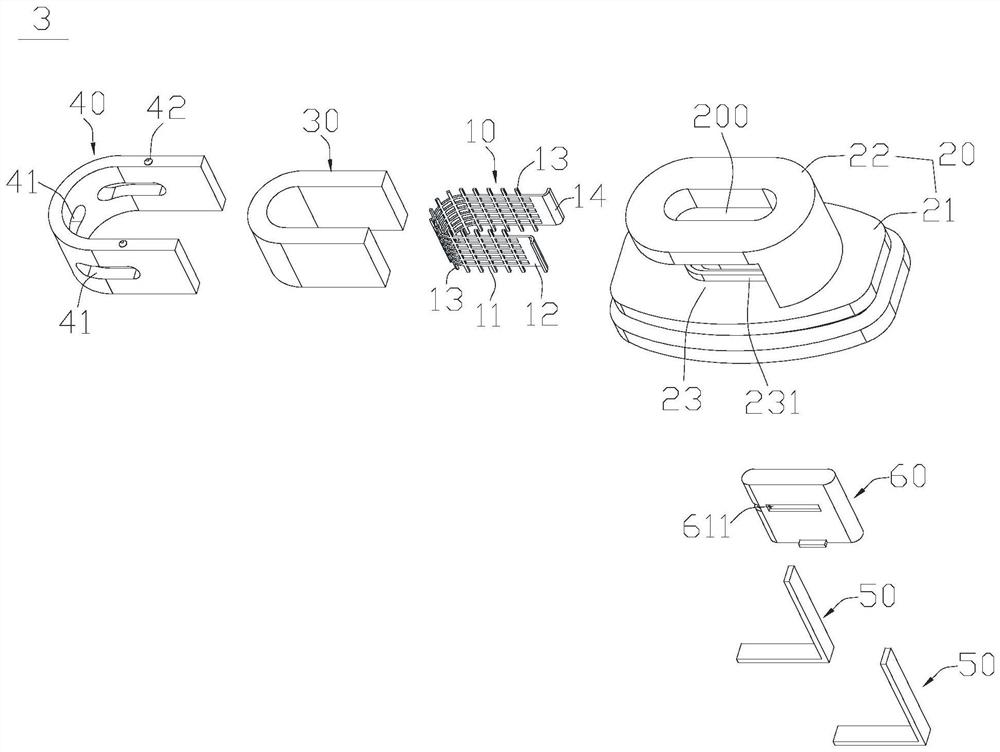
[0040] Such as figure 1 , 2 As shown, an atomizing device according to an embodiment of the present invention includes a housing 1 , a bottom shell 2 and an atomizing unit 3 .

[0041] The housing 1 is a hollow cylindrical structure and may include a first end and a second end opposite to each other. The housing 1 is provided with an isolated air duct 101 and a liquid storage tank 102. The air duct 101 is located in the middle of the housing 1 and extends along the length of the housing 1. The inner channel of the air duct 101 is an air duct. The liquid storage chamber 102 surrounds the outer periphery of the air duct 101 and is used for storing e-liquid. The first end of the shell 1 is provided with an air outlet 10...


PUM


Abstract

The invention discloses an atomization unit and an atomization device. The atomization unit comprises a net-shaped U-shaped heating piece, a supporting and fixing base with a central through hole, liquid guide cotton and a side sealing piece. The supporting and fixing base comprises a base and a supporting column body arranged on the base, and a center through hole penetrates through the supporting column body and the base. A U-shaped notch is formed in the side face of the supporting column body. The U-shaped heating sheet is arranged in the notch and abuts against the base; the liquid guidecotton wraps the outer side surface, far away from the central through hole, of the U-shaped heating sheet; the side sealing piece is matched in the notch to fix the liquid guide cotton between the side sealing piece and the U-shaped heating piece; and at least one liquid guide hole communicated with the liquid guide cotton is formed in the side sealing piece. According to the invention, the heating body is supported and fixed on the supporting and fixing base in a lateral assembly manner, and the liquid guide cotton and the heating body are fixed on the supporting and fixing base through thelateral sealing piece, so that the liquid guide cotton is in full contact with the heating body and is prevented from being extruded and deformed; thinning arrangement of the heating body is facilitated, and the material selection range is expanded.

Description

technical field [0001] The invention relates to the technical field of atomization, in particular to an atomization unit and an atomization device. Background technique [0002] Heating atomization can disperse the liquid into smaller particles, making the liquid molecules more dispersed in space. It is widely used in industries such as medical care, agriculture, home appliances, consumer electronics, etc., and the field of heating atomization is easy to implement. Most liquids can be atomized and have been widely used in recent years. As the heating body, the core component of heating atomization, innovation is particularly important. [0003] At present, the most widely used heating elements in the field of heating atomization are mainly divided into two types: one is a helical heating element formed by a spiral heating wire, and the other is a mesh heating element. When the mesh heating body is assembled with the fluid-conducting cotton, most of them are assembled on th...

Claims


Application Information

Patent Timeline
Patent Type & Authority Applications(China)
IPC IPC(8): A24F40/46A24F40/40A24F40/10A24F47/00
CPCA24F40/10A24F40/40A24F40/46A24F47/00
Inventor 汪小蝶
Owner SHENZHEN HUACHENGDA PRECISION IND CO LTD
Learn More