Solid-liquid separation device for kitchen garbage

A technology for solid-liquid separation and kitchen waste, applied in centrifuges, transportation and packaging, solid waste removal, etc., can solve problems such as inability to separate kitchen waste from solid-liquid and reduce friction

Pending Publication Date: 2021-03-16
王浩冰
View PDF1 Cites 0 Cited by
  • Summary
  • Abstract
  • Description
  • Claims
  • Application Information

AI Technical Summary

Problems solved by technology

[0006] Aiming at the deficiencies of the prior art, the present invention provides a kitchen waste solid-liquid separation device, which solves the problem that the existing device cannot completely separate the kitchen waste from solid and liquid, and achieves the purpose of crushing the waste, which is convenient for subsequent The processing of garbage can further separate the solid and liquid of the garbage inside the inner frame, and realize the function of separating the residual water attached to the surface of the garbage. The recovery of the impact device realizes the repeated impact of the garbage to remove water. function, and reduce the friction between the inner frame and the outer frame to prolong the service life of the inner frame

Method used


Image

  • Solid-liquid separation device for kitchen garbage
  • Solid-liquid separation device for kitchen garbage
  • Solid-liquid separation device for kitchen garbage

Examples


Embodiment 1

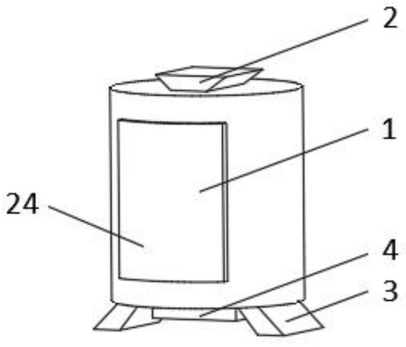
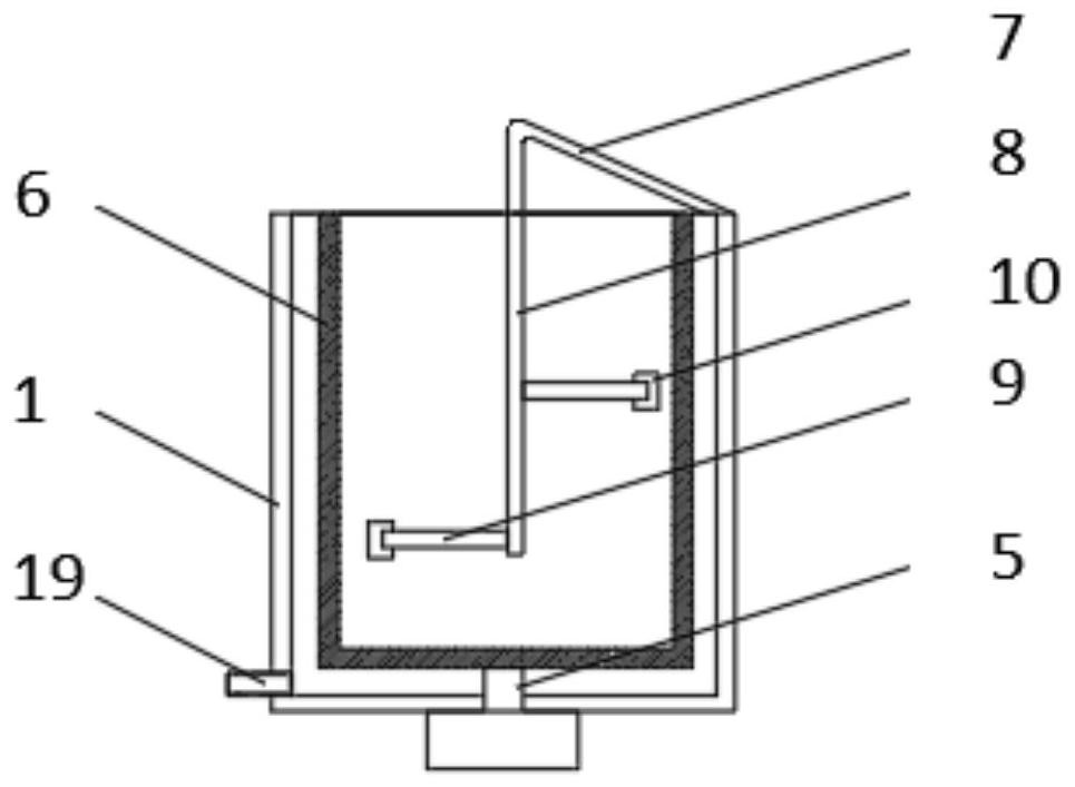
[0036] see Figure 1-3 , the present invention provides a technical solution: one comprising an outer frame 1, the top of the outer frame 1 is connected with a feed port 2, the bottom of the outer frame 1 is symmetrically installed with an underframe 3, and the side of the outer frame 1 close to the underframe 3 A motor 4 is installed, and the output end of the motor 4 is rotatably connected with a rotating rod 5, one end of the rotating rod 5 runs through the bottom of the outer frame 1, and the end of the rotating rod 5 away from the motor 4 is fixedly connected with an inner frame 6, which is an elastic mesh , an extension rod 7 is installed on the inner wall of the outer frame 1 close to the discharge port 2, and the end of the extension rod 7 away from the outer frame 1 is fixedly connected with a support column 8, and a bracket 9 is installed on the outside of the support column 8, and the bracket 9 is far away from the support column One end of 8 is connected with fixed...

Embodiment 2

[0039] see Figure 1-5 , the present invention provides a technical solution: on the basis of the first embodiment, the inner wall of the groove 14 is symmetrically installed with a first limit block 15, and the inside of the groove 14 is equipped with an impact device 16, and the impact device 16 includes an impact block 161 One side of the impact block 161 is fixedly connected with a movable plate 162, and one side of the movable plate 162 is symmetrically installed with a second limit block 163, and the side of the movable plate 162 away from the impact block 161 is fixedly connected with a spring 164, and the spring 164 is away from the movable One end of the plate 162 is connected to the bottom of the groove 14 .

[0040] The inner wall of the groove 14 is symmetrically provided with a chute 20 away from the position of the first limiting block 15, and one end of the chute 20 is rotatably connected with a baffle 21, and the end of the baffle 21 away from the chute 20 is r...

Embodiment 3

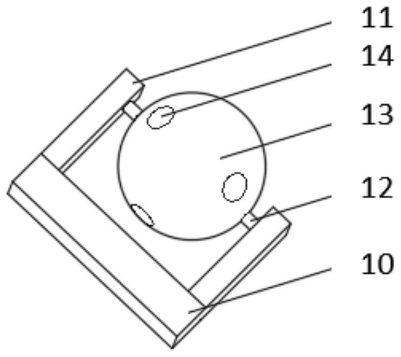
[0044] see Figure 1-7 , the present invention provides a technical solution: on the basis of Embodiment 2, a support device 17 is installed inside the cleaning ball 13, the support device 17 includes a limit ball 171, and a support frame 172 is evenly installed on the outside of the limit ball 171, A cutter head 173 is installed on the outside of the support frame 172 , and a blade 174 is installed on one side of the cutter head 173 .

[0045] During use, the cleaning ball 13 squeezes the kitchen waste toward the inner frame 6, and the cleaning ball 13 is depressed to the inside of the support frame 172 by the extrusion force from the garbage. 172 exposes the surface of cleaning ball, and after the blade 174 that is installed on the support frame 172 fully contacts with rubbish, rubbish is cut, after cleaning ball 13 rotates with inner frame 6, the support frame 172 of depression is no longer with inner frame 6 Contact, the sunken cleaning ball 13 is not subject to extrusion...


PUM


Abstract

The invention discloses a solid-liquid separation device for kitchen garbage. The solid-liquid separation device comprises an outer frame, wherein the top of the outer frame communicates with a feeding port, and a bottom frame is symmetrically arranged at the bottom of the outer frame; a motor is arranged on the side, close to the bottom frame, of the outer frame; the output end of the motor is rotationally connected with a rotating rod, and one end of the rotating rod penetrates through the bottom of the outer frame; the end, away from the motor, of the rotating rod is fixedly connected withan inner frame, and the inner frame is an elastic net; an extending rod is arranged at the position, close to a discharging port, of the inner wall of the outer frame, and the end, away from the outerframe, of the extending rod is fixedly connected with a supporting column; a support is arranged on the outer side of the supporting column, and the end, away from the supporting column, of the support is connected with a fixing frame; and fixing rods are symmetrically arranged on one side of the fixing frame. The invention relates to the technical field of solid-liquid separation. According to the solid-liquid separation device for the kitchen garbage, the purpose of solid-liquid separation of the garbage is achieved, and the function of crushing the garbage can be achieved.

Description

technical field [0001] The invention relates to the technical field of solid-liquid separation, in particular to a solid-liquid separation device for kitchen waste. Background technique [0002] As one of the most common household wastes, kitchen waste has great reuse value. Common kitchen waste disposal methods include composting or direct burial, and crushing the waste into slag will facilitate subsequent treatment. However, kitchen waste There is a lot of waste water in the kitchen waste, which often leads to insufficient crushing. On the other hand, kitchen waste contains a lot of waste oil, and the current oil-water separation method often leads to waste liquid in the separated oil, which greatly reduces its utilization value. [0003] For example, the invention of Chinese patent CN111139902A proposes a kind of invention which relates to the technical field of kitchen appliances, which can separate most of the processed kitchen waste from solid to liquid, so as to avoid...

Claims


Application Information

Patent Timeline
Patent Type & Authority Applications(China)
IPC IPC(8): B09B3/00B09B5/00B04B5/10B02C18/08
CPCB09B5/00B04B5/10B02C18/0092B02C18/08B02C2201/06B09B3/80
Inventor 王浩冰
Owner 王浩冰
Why Eureka
Try Eureka