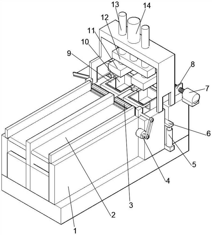
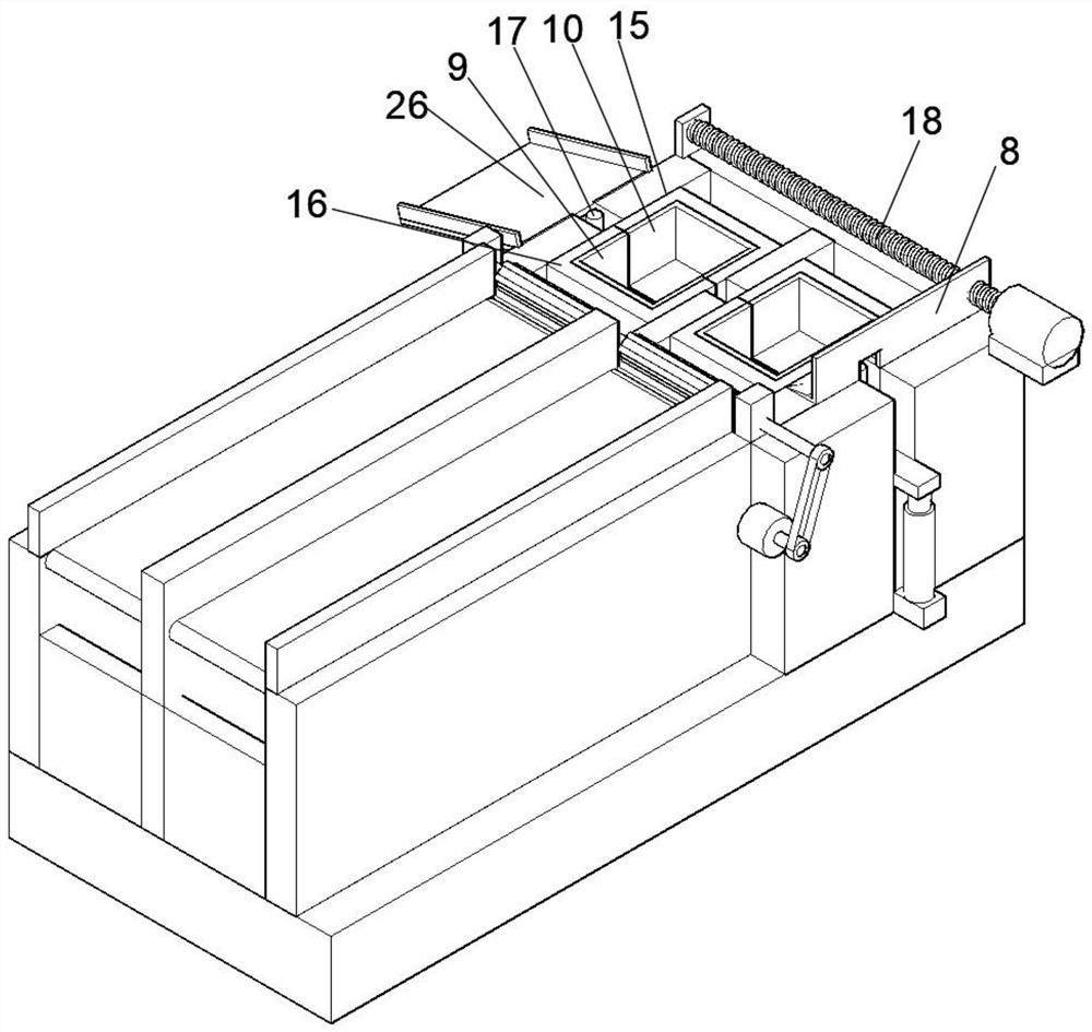
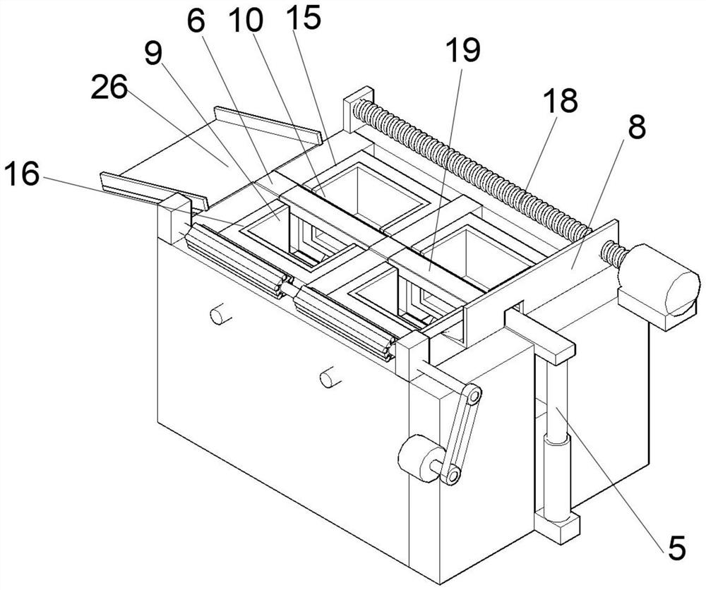
Automatic discharging and stamping equipment

A technology of stamping equipment and automatic blanking, applied in the stamping field, can solve problems such as affecting the processing progress, difficult to remove, affecting product quality, etc., to achieve the effect of improving product quality and reducing damage

Inactive Publication Date: 2021-03-16
HEFEI DEJIE ENERGY CONSERVATION & ENVIRONMENTAL PROTECTION TECH CO LTD
View PDF0 Cites 6 Cited by
  • Summary
  • Abstract
  • Description
  • Claims
  • Application Information

AI Technical Summary

Problems solved by technology

[0002] Stamping is a forming process that uses a press to act on the plates, strips, pipes, and profiles between the molds to cause plastic deformation or separation, and finally obtain stamped parts with a set shape and size. Stamping processing is by means of conventional or The power of the special stamping equipment makes the sheet material deformed directly by the deformation force in the mold, so as to obtain the production technology of product parts with a certain shape, size and performance, so that the material can fit the inner cavity of the lower mold after stamping, and make the required Since the parts are usually metal, they will fit the lower mold after stamping, or they will be stuck in the lower mold, which is difficult to remove, seriously affecting the processing progress, and forced removal will cause the processed parts to deform and affect product quality.

Method used


Image

  • Automatic discharging and stamping equipment
  • Automatic discharging and stamping equipment
  • Automatic discharging and stamping equipment

Examples


Embodiment Construction

[0028] The following will clearly and completely describe the technical solutions in the embodiments of the present invention with reference to the accompanying drawings in the embodiments of the present invention. Obviously, the described embodiments are only some, not all, embodiments of the present invention. Based on the embodiments of the present invention, all other embodiments obtained by persons of ordinary skill in the art without making creative efforts belong to the protection scope of the present invention.

[0029] In the description of the present invention, it should be noted that the orientation or positional relationship indicated by the terms "vertical", "upper", "lower" and "horizontal" are based on the orientation or positional relationship shown in the drawings, and are only for It is convenient to describe the present invention and simplify the description, but does not indicate or imply that the device or element referred to must have a specific orientati...


PUM


Abstract

The invention discloses automatic discharging and stamping equipment. The equipment comprises a machine body, and a feeding mechanism, a stamping mechanism and a material taking mechanism are arrangedon the machine body; the feeding mechanism comprises a conveying belt; and the stamping mechanism is arranged at one side of the conveying belt and comprises an upper die and a lower die, the lower die is formed by splicing a first lower die body and a second lower die body, and the bottom of the first lower die body and the bottom of the second lower die body are sleeved with a first supportingframe and a second supporting frame correspondingly. The material taking mechanism comprises a control panel, the control panel is arranged below the first supporting frame and the second supporting frame, and a first hydraulic cylinder is installed at one side of a pushing plate. The first lower die body and the second lower die body are opened towards the two sides, a stamped part is unlocked, the part is ejected out through upward movement of the pushing plate, automatic discharging is conducted, convenience and rapidness are achieved, the situation that the part is clamped in a die is avoided, damage to the part is reduced, and the product quality is improved.

Description

technical field [0001] The invention relates to the technical field of stamping, in particular to an automatic blanking stamping equipment. Background technique [0002] Stamping is a forming process that uses a press to act on the plates, strips, pipes, and profiles between the molds to cause plastic deformation or separation, and finally obtain stamped parts with a set shape and size. Stamping processing is by means of conventional or The power of the special stamping equipment makes the sheet material deformed directly by the deformation force in the mold, so as to obtain the production technology of product parts with a certain shape, size and performance, so that the material can fit the inner cavity of the lower mold after stamping, and make the required Since the parts are usually metal, they will fit the lower mold after stamping, or they will be stuck in the lower mold, making it difficult to remove, seriously affecting the processing progress, and forcibly removing...

Claims


Application Information

Patent Timeline
Patent Type & Authority Applications(China)
IPC IPC(8): B21D22/02B21D43/12B21D45/04
CPCB21D22/02B21D43/12B21D45/04
Inventor 卢世军张厚芳
Owner HEFEI DEJIE ENERGY CONSERVATION & ENVIRONMENTAL PROTECTION TECH CO LTD
Why Eureka
Try Eureka