Supercharge Your Innovation With Domain-Expert AI Agents!

A fully automatic lug trimming device

A trimming device and fully automatic technology, applied in lighting devices, shearing devices, lighting devices, etc., can solve the problems of low degree of automation, poor practicability, time-consuming and labor-intensive, etc., and achieve a high degree of automation, strong practicability, and reduced The effect of labor

Active Publication Date: 2022-05-27
湖南电将军新能源有限公司
View PDF9 Cites 0 Cited by
  • Summary
  • Abstract
  • Description
  • Claims
  • Application Information

AI Technical Summary

Problems solved by technology

[0004] However, in the actual use process, the existing lug trimming device has a low degree of automation, time-consuming and labor-intensive, and poor practicability

Method used


Image

  • A fully automatic lug trimming device
  • A fully automatic lug trimming device
  • A fully automatic lug trimming device

Examples


Embodiment 1

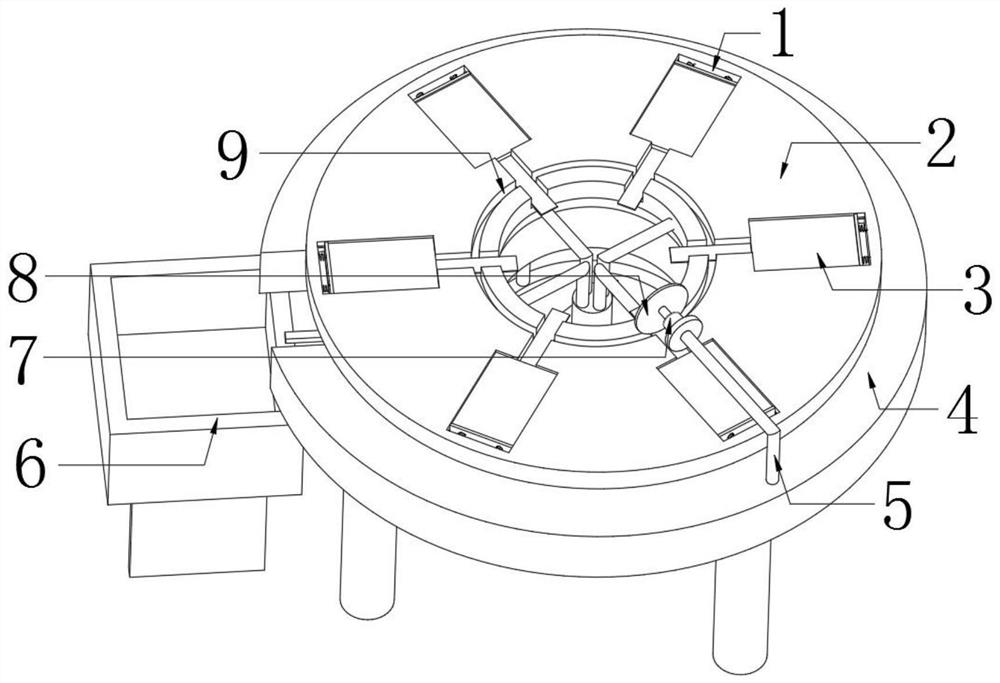
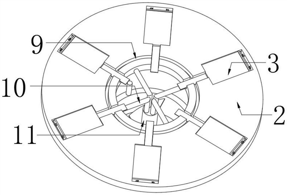
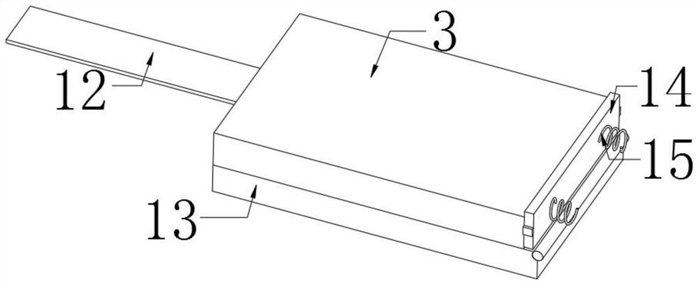
[0029] refer to Figure 1-4 , an automatic pole ear trimming device, including a workbench 4, the bottom outer wall of the workbench 4 is fixed with fixed rods at equal distances by bolts, and the bottom outer wall of the fixed rod is fixed with the same storage cylinder by bolts. The bottom outer wall is fixed with a second motor 20 by bolts, the output shaft of the second motor 20 is connected with a rotating rod 11 through a coupling, and the top outer wall of the rotating rod 11 is fixed with equidistantly distributed connecting rods 10 by bolts. One end is fixed with the same turning plate 2 by bolts, the top outer wall of the turning plate 2 is provided with installation holes 1 distributed at equal distances, the inner wall of the installation hole 1 is fixed with a baffle frame by bolts, and the inner wall of the installation hole 1 is connected by hinges. Plate 13, the top outer wall of the connecting plate 13 is provided with the core 3, the outer wall of one side of...

Embodiment 2

[0040] refer to Figure 5 , an automatic pole ear trimming device, including a workbench 4, the bottom outer wall of the workbench 4 is fixed with fixed rods at equal distances by bolts, and the bottom outer wall of the fixed rod is fixed with the same storage cylinder by bolts. The bottom outer wall is fixed with a second motor 20 by bolts, the output shaft of the second motor 20 is connected with a rotating rod 11 through a coupling, and the top outer wall of the rotating rod 11 is fixed with equidistantly distributed connecting rods 10 by bolts. One end is fixed with the same turning plate 2 by bolts, the top outer wall of the turning plate 2 is provided with installation holes 1 distributed at equal distances, the inner wall of the installation hole 1 is fixed with a baffle frame by bolts, and the inner wall of the installation hole 1 is connected by hinges. Plate 13, the top outer wall of the connecting plate 13 is provided with the core 3, the outer wall of one side of t...


PUM


Abstract

The invention belongs to the technical field of tab trimming, in particular to a fully automatic tab trimming device. Aiming at the problems of low automation and time-consuming and labor-consuming problems of the existing tab trimming devices, the following proposals are proposed, including the workbench. The bottom outer wall of the workbench is fixed with equidistant fixed rods through bolts, the bottom outer wall of the fixed rod is fixed with the same storage cylinder through bolts, and the bottom outer wall of the storage cylinder is fixed with a second motor through bolts. The output shaft of the second motor is connected with a rotating rod through a coupling. While the turning plate of the present invention is rotating, the lug body can be trimmed and cut by using the first motor combined with the cutting knife to cooperate with the cutting groove, so as to ensure that all the lug bodies have a uniform length, and no manual work on the lug body is required. For trimming, people only need to be responsible for simple placement and supervision. When the trimming of the lug body is completed, some waste materials will fall directly into the storage cylinder.

Description

technical field [0001] The invention relates to the technical field of pole ear trimming, in particular to an automatic pole ear trimming device. Background technique [0002] The battery is divided into positive and negative poles, and the pole ear is the metal conductor that leads the positive and negative poles from the battery core. In layman's terms, the ears of the positive and negative poles of the battery are the contact points during charging and discharging. This contact point is not the copper sheet we see on the outside of the battery, but a connection inside the battery. The tabs are divided into three materials. The positive electrode of the battery is made of aluminum (Al) material, the negative electrode is made of nickel (Ni) material, and the negative electrode is also made of nickel-plated copper (Ni—Cu) material. to make. [0003] In the production process of the battery, the size of the battery is generally fixed first, and then the tabs are welded on ...

Claims


Application Information

Patent Timeline
Patent Type & Authority Patents(China)
IPC IPC(8): B23D19/00B23D33/00B23D33/02F21V33/00
CPCB23D19/00B23D33/02B23D33/00F21V33/00
Inventor 吴吉强宋桂军熊来龙胡贵才胥庆
Owner 湖南电将军新能源有限公司
Features
  • R&D
  • Intellectual Property
  • Life Sciences
  • Materials
  • Tech Scout
  • Unparalleled Data Quality
  • Higher Quality Content
  • 60% Fewer Hallucinations
Learn More