Direct-current charging gun electronic lock driving circuit

A DC charging and driving circuit technology, applied in charging stations, electric vehicles, electric vehicle charging technology, etc., can solve problems such as locking or unlocking, locking or unlocking without control of electronic locks, and not locking or unlocking electronic locks , to achieve reliable locking and unlocking, strong practical value and marketing value, and the effect of small footprint

Pending Publication Date: 2021-03-16
LISHEN (QINGDAO) NEW ENERGY CO LTD
View PDF0 Cites 3 Cited by
  • Summary
  • Abstract
  • Description
  • Claims
  • Application Information

AI Technical Summary

Problems solved by technology

[0004] However, based on the existing technical solutions, when the battery management system BMS is required to control the locking or unlocking of the electronic lock, it may happen that the BMS does not control the locking or unlocking of the electronic lock when it should be locked or unlocked, and when it should not be locked or unlocked BMS controls the locking or unlocking of the electronic lock
[0005] The reason for the above problems is: the existing tech

Method used


Image

  • Direct-current charging gun electronic lock driving circuit
  • Direct-current charging gun electronic lock driving circuit
  • Direct-current charging gun electronic lock driving circuit

Examples


Embodiment Construction

[0068] In order to make the technical means realized by the present invention easier to understand, the present application will be further described in detail below in conjunction with the accompanying drawings and embodiments. It should be understood that the specific embodiments described here are only used to explain the related application, not to limit the application. In addition, it should be noted that, for ease of description, only parts relevant to the present application are shown in the drawings.

[0069] It should be noted that, in the case of no conflict, the embodiments in the present application and the features in the embodiments can be combined with each other. The present application will be described in detail below with reference to the accompanying drawings and embodiments.

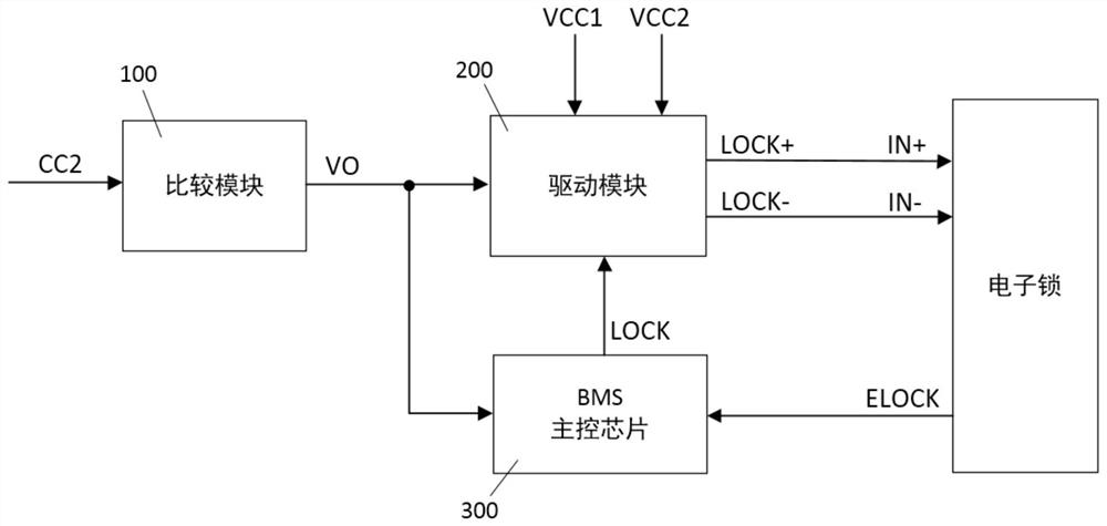
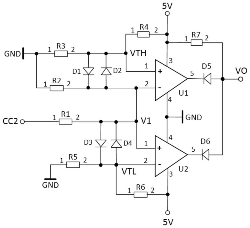
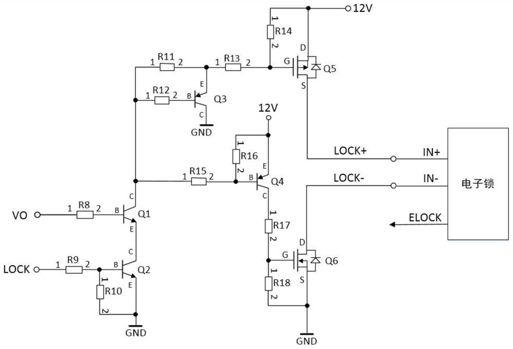
[0070] see Figure 1 to Figure 3 , the present invention provides a DC charging gun electronic lock drive circuit, including a lock comparison module 100, a drive module 200 and a...


PUM


Abstract

The invention discloses a direct-current charging gun electronic lock driving circuit. The circuit comprises a locking comparison module, the input end of which is connected with the charging connection confirmation end CC2 of a direct-current charging gun socket, and the output end of which is connected with the first input end of a driving module and the first input end of a BMS main control chip; and the circuit further comprises a driving module, and the first power supply input end and the power supply input end of the driving module are respectively connected with an external direct-current power supply; the first input end of the driving module is connected with the output end of the locking comparison module, the second input end of the driving module is connected with the output end LOCK of the BMS main control chip, and the output end LOCK + and the output end LOCK- of the driving module are connected with the positive electrode input end and the negative electrode input endof an electronic lock respectively; the first input end of the BMS main control chip is connected with the output end of the locking comparison module, and the second input end of the BMS main controlchip is connected with the position feedback output end ELOCK of the electronic lock. The electronic lock can be safely and reliably driven to be locked and unlocked.

Description

technical field [0001] The invention relates to the technical field of battery management, in particular to a driving circuit for an electronic lock of a DC charging gun. Background technique [0002] The battery management system (Battery Management System, hereinafter referred to as BMS) is a battery protection device and a bridge between the battery and the load terminal. According to the actual use status of the battery monitored online, it provides protection functions such as overcharge, overdischarge, and overtemperature for the battery to ensure Batteries are used safely. The battery management system BMS is widely used in many fields such as electric vehicles, communication base stations, and robots. [0003] Taking electric vehicles as an example, according to the requirements of the new national standard GB / T18487.1-2015 (General Requirements for Electric Vehicle Conductive Charging System Part 1), an electronic lock function must be added to the DC charging gun ...

Claims


Application Information

Patent Timeline
IPC IPC(8): B60L53/16E05B47/00
CPCB60L53/16E05B47/0001Y02T10/70Y02T10/7072Y02T90/14
Inventor 张明艳
Owner LISHEN (QINGDAO) NEW ENERGY CO LTD
Why Eureka
Try Eureka