Built-in sorbent floating head type adsorbent bed refrigeration unit

A refrigeration unit and adsorption bed technology, applied in the field of adsorption refrigeration, can solve the problems of reduced adsorption refrigeration performance, inability to reduce mass transfer resistance, and easy leakage, etc., to achieve strong adaptability to alternating thermal stress, strong industrial application value, and guarantee The effect of stable operation

Inactive Publication Date: 2009-09-16
ZHENGZHOU UNIV
View PDF0 Cites 5 Cited by
  • Summary
  • Abstract
  • Description
  • Claims
  • Application Information

AI Technical Summary

Problems solved by technology

[0002] At present, adsorption refrigeration technology is increasingly becoming the research focus of people, but there are two major problems in this technology: 1. When the adsorption refrigeration system is working, the adsorption refrigeration unit is alternately heated and cooled. The temperature of the body and the material are not consistent, and alternating thermal stress is generated between them, which is easy to damage the connection of the tube sheet of the adsorption refrigeration unit and cause leakage of the adsorption refrigeration unit; it is known from the experiment that even a small amount of non-condensable gas enters the The interior of the adsorption refrigeration unit will also greatly reduce the refrigeration performance of the adsorption refrigeration system; the above reveals that the structural design of the adsorption refrigeration unit is still unscientific and imperfect; 2. Since the adsorbent needs to be heated or cooled alternately to achieve mechanical compression Therefore, the cooling or heating of a single adsorption refrigeration unit is discontinuous. In order to improve heat utilization efficiency and continuous refrigeration or heating, two or more adsorption refrigeration units are often used together to alternately heat or cool. And through the complex pipeline valve system to realize the recovery of heat and mass, so as to achieve continuous cooling or heating; although domestic and foreign scholars have proposed many technical solutions, the pipeline valve system is complex, prone to leakage, and the heat transfer efficiency is low , so it is still difficult to realize continuous adsorption refrigeration
[0004] 1. The aspect ratio of the mass transfer channel in the adsorption bed is too large. When the cycle period is short, the adsorbent far away from the inlet cannot play its full role due to the lack of refrigerant vapor around it. In order to let the adsorbent there play its full role , the cycle time will be extended again, but this will lead to a decrease in the refrigeration power and COP of the adsorption refrigeration unit;
[0005] 2. In order to ensure that the refrigerant vapor can be fully condensed when passing through the adsorption bed, the length of the condenser should not be too short; since the adsorption bed condenser adopts the same diameter as the adsorption bed, the internal space volume of the condenser may exceed an optimum Volume; too large condenser volume will affect the refrigeration performance of the system, because the refrigerant vapor pressure in the unit changes periodically when the system is working, then part of the refrigerant vapor will remain in the condenser, and this part of the refrigerant will not only Does not participate in refrigeration and will also consume part of the adsorption capacity of the adsorbent;
[0006]3. Since the adsorption bed is a slender tube with a relatively large length and diameter, there are some problems in selecting the filling thickness of the adsorbent; if the inner diameter of the tube is fixed, use a thicker tube Adsorbents with higher heat transfer distances will increase the thermal resistance and increase the mass transfer resistance. Although the heat transfer area can be increased by using inner fins, the mass transfer resistance cannot be reduced; the use of thinner adsorbents can shorten the heat transfer The distance reduces the heat transfer resistance, but it will cause the metal specific heat capacity of the adsorption bed to be larger, and the space inside the adsorption bed will be larger, causing part of the refrigerant vapor to "stay" and reduce its adsorption refrigeration performance.

Method used


Image

  • Built-in sorbent floating head type adsorbent bed refrigeration unit
  • Built-in sorbent floating head type adsorbent bed refrigeration unit

Examples


Embodiment Construction

[0018] The technical solutions of the present invention will be described in further detail below through specific implementation methods.

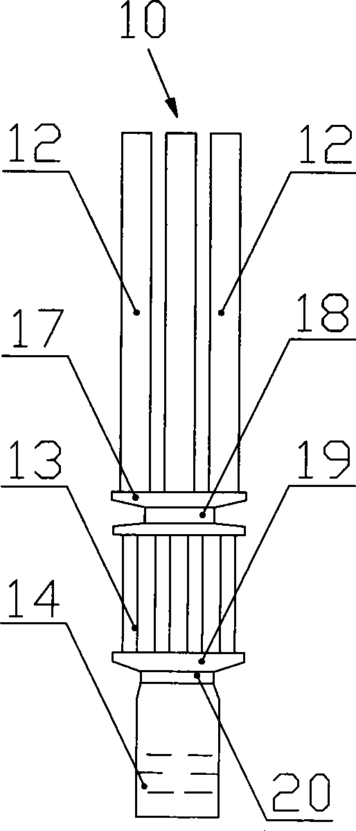
[0019] In order to reduce the thermal stress on the tube sheet of the adsorption bed and improve the reliability of the system, the present invention combines the technical advantages of each adsorption refrigeration unit and proposes a new type of adsorption bed refrigeration unit with a built-in adsorbent floating head structure, such as figure 1 Shown: a built-in adsorbent floating head type adsorption bed refrigeration unit 10, the built-in adsorbent floating head type adsorption bed refrigeration unit 10 includes an adsorption bed 12 connected in sequence, a heat-insulated and connected closed body 17, a condenser 13, an adiabatic connected and sealed body body 19 and evaporator 14;

[0020] The adsorption bed 12 is composed of six outer finned tubes with an outer diameter of 20mm, and the six outer finned tubes are evenly distribute...


PUM


Abstract

The invention provides a built-in sorbent floating head type adsorbent bed refrigeration unit. The refrigeration unit comprises an adsorbent bed, an insulation connective closed body, a condenser, an adiathermance connective closed body and an evaporator, wherein the adsorbent bed is formed by at least two outer fin tubes; the sorbent is solidified on the inner wall of the outer fin tubes of the adsorbent bed; a mass transfer channel is arranged in the center of the outer fin tubes of the adsorbent bed; the condenser is formed by at least two outer fin tubes; the evaporator is formed by at least one outer fin tube; upper ends of the outer fin tubes of the adsorbent be are closed; lower ends of the outer fin tubes of the adsorbent bed are communicated with the upper end of the insulation connective closed body; the lower end of the insulation connective closed body is communicated with upper ends of the outer fin tubes of the condenser; lower ends of the outer fin tubes of the condenser are communicated with the upper end of the adiathermance connective closed body; the lower end of the adiathermance connective closed body is communicated with the upper end of the outer fin tube of the evaporator; and the lower end of the outer fin tube of the evaporator is closed. The refrigeration unit has scientific structure design, strong capability of adapting to reversed heat stress, does not leak in operation, and has prominent adsorbent refrigeration effect.

Description

technical field [0001] The invention relates to an adsorption refrigeration unit, in particular to a built-in adsorbent floating head type adsorption bed refrigeration unit, which belongs to the technical field of adsorption refrigeration. Background technique [0002] At present, adsorption refrigeration technology is increasingly becoming the research focus of people, but there are two major problems in this technology: 1. When the adsorption refrigeration system is working, the adsorption refrigeration unit is alternately heated and cooled. The temperature of the body and the material are not consistent, and alternating thermal stress is generated between them, which is easy to damage the connection of the tube sheet of the adsorption refrigeration unit and cause leakage of the adsorption refrigeration unit; it is known from the experiment that even a small amount of non-condensable gas enters the The interior of the adsorption refrigeration unit will also greatly reduce ...

Claims


Application Information

Patent Timeline
Patent Type & Authority Applications(China)
IPC IPC(8): F25B17/08F25B39/04F25B39/02
CPCY02B30/64Y02A30/27Y02B30/00
Inventor 魏新利孟祥睿王定标张军马新灵
Owner ZHENGZHOU UNIV
Why Eureka
Try Eureka