A floating communication base station with self-generating water surface

A communication base station and self-generating technology, applied in the field of communication engineering, can solve the problems of difficulty in establishing base stations and poor signal resources, etc.

Active Publication Date: 2021-10-26
深圳市瑞迅通信息技术有限公司
View PDF0 Cites 0 Cited by
  • Summary
  • Abstract
  • Description
  • Claims
  • Application Information

AI Technical Summary

Problems solved by technology

[0005] In order to solve the technical problems existing in the background technology, the present invention proposes a self-generating floating communication base station on the water surface, which solves the problem that it is very difficult to establish a base station on the water surface on the island and some locations, and the problem of poor signal resources

Method used


Image

  • A floating communication base station with self-generating water surface
  • A floating communication base station with self-generating water surface
  • A floating communication base station with self-generating water surface

Examples


Embodiment example 1

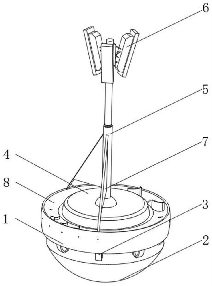
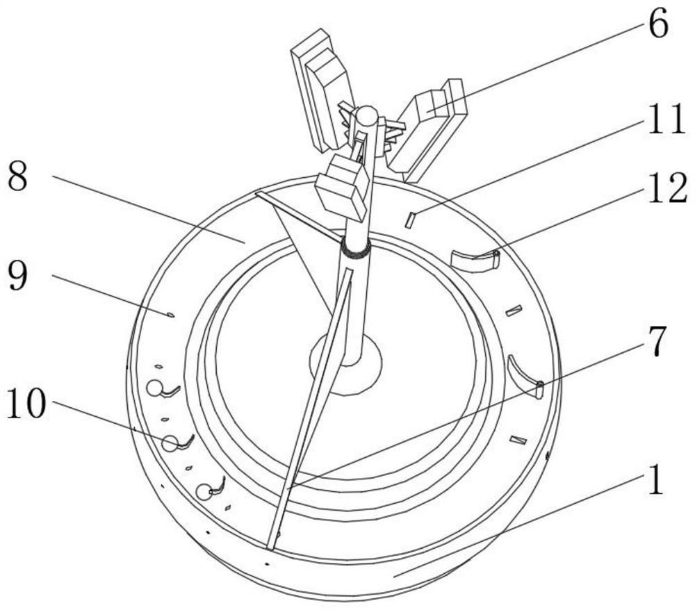
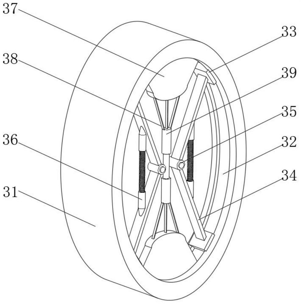
[0030] Such as Figure 1-6 As shown, a kind of water surface self-generating floating communication base station proposed by the present invention includes a buoy base 1, a bottom buoy 2 is arranged under the buoy base 1, a spherical universal joint is arranged on the bottom of the buoy base 1, and the buoy base 1 It is movably connected with the bottom float 2 through a spherical universal joint. There is a buffer zone between the float base 1 and the bottom float 2. A buffer device 3 is installed inside the buffer zone. An inner ring groove 8 is opened on the upper side of the float base 1. The center position of the top of the float base 1 is fixedly connected to the signal pole 5 through the mounting seat 4, and the communication base station body 6 is installed on the top of the signal pole 5, and the two sides of the float base 1 are respectively provided with airflow holes 9 and 8 in the inner ring groove 8. The air flow slot 11, the wind direction plate 7 is installed ...

Embodiment example 2

[0039] Such as Figure 1-6As shown, on the basis of the first embodiment, there are 9 airflow holes 9, 5 airflow grooves 11, two wind direction plates 7, and the wind direction plates 7 are arranged on the side close to the airflow holes 9, and the two wind direction plates The angle between the plates 7 is set to 150°, and the device at this time can be stronger by the side wind blown into by the device;

[0040] When the movable ball is installed between the airflow holes 9, the curved arc deflector 10 is installed on the outside of the movable ball, and the movable deflector 12 is installed by the rotating column between the air flow slots 11. The curved arc deflector 10 of the device and the movable deflector When the deflector 12 is located in the center and does not move, the strong side airflow will cause the device to generate a force of continuous up and down, so that the lower buffer mechanism can complete more deformation.

[0041] When the curved deflector 10 inst...

Embodiment example 3

[0043] Such as Figure 1-6 As shown, on the basis of the implementation case 1 and the implementation case 2, there are 6 airflow holes 9, 5 airflow slots 11, two wind direction plates 7, and the wind direction plates 7 are arranged on the side close to the air flow holes 9 , the angle between the two wind direction plates 7 is set to 120°, the device at this time can be balanced by the side wind blown in by the device, and the device runs more stably.

[0044] In the present invention, it should be noted that the device is arranged in upper and lower parts, and the upper float base 1 and its upper components are mainly used to support the stable operation of the communication base station. The communication base station body 6 of the device is set in three directions, which can ensure The range covers the signal, and the signal will not be deteriorated due to the movement of the device.

[0045] It should be noted that the airflow hole 9 and the airflow groove 11 provided on...


PUM


Abstract

The invention discloses a water surface self-generating floating communication base station, which comprises a buoy base, a bottom float is arranged under the buoy base, a spherical universal joint is arranged on the bottom of the buoy base, and the buoy base passes through a spherical The universal connector is movably connected with the bottom float, and there is a buffer zone between the float base and the bottom float, and a buffer device is installed inside the buffer zone, and an inner ring groove is opened on the upper side of the float base. The invention relates to the technical field of communication engineering. The self-generating floating communication base station on the water surface solves the problem that it is very difficult to establish a base station on the water surface on the island and some locations, and the signal resources are poor. Through the purpose of self-generating reset, the device can be freed from floating on the water surface If there is no power supply, the device will stop working. The device can effectively use wave energy to deform the internal dielectric elastic body, so as to achieve the purpose of continuous power generation, and the signal will not be deteriorated due to the movement of the device.

Description

technical field [0001] The invention relates to the technical field of communication engineering, in particular to a water surface self-generating floating communication base station. Background technique [0002] With the gradual development of communication technology, in order to improve the signal quality of mobile phones, communication base stations are often set up on the ground; there are antennas on the communication base stations, which can receive signals from mobile phones and send signals to other base stations or mobile phones , in order to realize the signal transmission; the position of the antenna on the base station is fixed, but the antenna has a communication blind spot, how to adjust the position of the antenna so that the communication blind spot is not located in a densely populated location has become a research hotspot. [0003] Most of the existing communication base stations are set up on the ground. Some households and ships along the waterside do ...

Claims


Application Information

Patent Timeline
Patent Type & Authority Patents(China)
IPC IPC(8): B63B35/44H04Q1/02
CPCB63B35/44B63B2035/4466H04Q1/02
Inventor 魏文慧
Owner 深圳市瑞迅通信息技术有限公司
Why Eureka
Try Eureka