
Color printing and spray painting structure and garment cloth dyeing equipment

A kind of dyeing equipment and inkjet technology, which is applied in the field of color printing inkjet structure and garment fabric dyeing equipment, to achieve the effect of avoiding excessive temperature, facilitating recycling, and improving recycling efficiency

Active Publication Date: 2021-03-16
湖南亚瑞特运动用品有限公司
View PDF6 Cites 0 Cited by
  • Summary
  • Abstract
  • Description
  • Claims
  • Application Information

AI Technical Summary

Problems solved by technology

[0003] The current fabric dyeing process mostly adopts the method of directly placing the fabric in the dyeing agent for dyeing. The dyed fabric is then dried in the sun, and finally cut and shaped for packaging. Although this dyeing method is fast, it cannot avoid the existence of The situation where the cloth is stained with the dye, which will cause spots and color differences after the cloth is dyed

Method used


Image

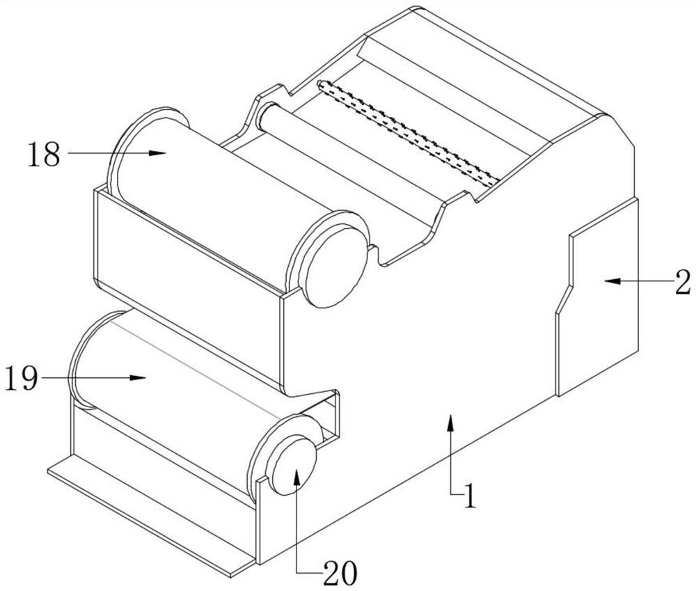
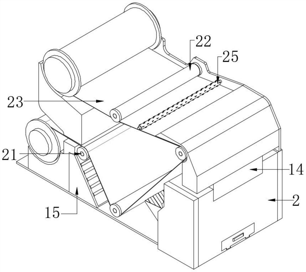
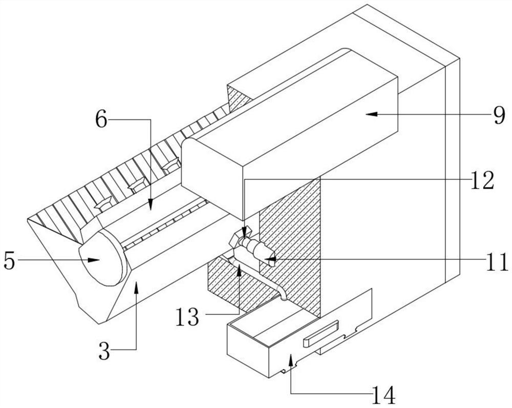
  • Color printing and spray painting structure and garment cloth dyeing equipment
  • Color printing and spray painting structure and garment cloth dyeing equipment
  • Color printing and spray painting structure and garment cloth dyeing equipment

Examples


Embodiment Construction

[0025] The following will clearly and completely describe the technical solutions in the embodiments of the present invention with reference to the accompanying drawings in the embodiments of the present invention. Obviously, the described embodiments are only some, not all, embodiments of the present invention. Based on the embodiments of the present invention, all other embodiments obtained by persons of ordinary skill in the art without making creative efforts belong to the protection scope of the present invention.

[0026] In addition, an element in the present invention is said to be "fixed" or "disposed on" another element, and it may be directly on another element or an intervening element may also exist. When an element is referred to as being "connected to" another element, it can be directly connected to the other element or intervening elements may also be present. The terms "vertical," "horizontal," "left," "right," and similar expressions are used herein for purp...


PUM


Abstract

The invention belongs to the technical field of color printing and spray painting, and particularly relates to a color printing and spray painting structure and garment cloth dyeing equipment. The following scheme is put forward currently, the color printing and spray painting structure comprises a color printing and spray painting box, a material collecting box is arranged on one side of the color printing and spray painting box, the interior of the material collecting box is in a leaking groove shape, and a falling plate is fixedly connected to the inner wall of one side of the material collecting box. The angles of the material collecting box and a spraying seat are adjusted through stretching and retracting of an electric telescopic rod, and the extending distance of the spraying seatis adjusted through an electric sliding rail, so that the optimal color printing and spray painting effect is achieved; in the color printing and spray painting process, the interior of the material collecting box is in the leaking groove shape, falling pigment can be collected to the maximum degree, the situation that the pigment falls to the exterior of the device and cannot be collected is avoided, flowing of the pigment can be accelerated through the falling plate, and the falling recycling efficiency of the pigment is improved; and the collected fallen pigment is quickly conveyed into a recycling box through a discharging pipe on the lower portion of the material collecting box, secondary recycling of the pigment is facilitated, and waste of the pigment is avoided.

Description

technical field [0001] The invention relates to the technical field of color printing and inkjet painting, in particular to a color printing and inkjet painting structure and clothing cloth dyeing equipment. Background technique [0002] Color printing refers to printing on the same page with plates of different colors to achieve the effect of color pictures. The original manuscripts such as texts, pictures, and photos are processed by plate making, ink application, and pressure to transfer ink to paper, fabrics, leather, etc. On the surface of the material, it is a technology to batch copy the contents of the original manuscript; inkjet painting is a basic and relatively traditional expression technique in the advertising industry. It has irreplaceable characteristics and advantages of other expression techniques. Compared with other hand-painted techniques, its expression is more delicate. True, it can express objects in a super-realistic way, and achieve the effect of a f...

Claims


Application Information

Patent Timeline
Patent Type & Authority Applications(China)
IPC IPC(8): D06B1/02D06B15/00D06B23/02D06B23/20D06C11/00
CPCD06B1/02D06B23/20D06B15/00D06B23/02D06C11/00
Inventor 罗剑锋
Owner 湖南亚瑞特运动用品有限公司
Learn More