Eureka AIR delivers breakthrough ideas for toughest innovation challenges, trusted by R&D personnel around the world.

Highway T-beam hogging moment grouting exhaust observation pipe

A highway and observation tube technology, applied in bridges, bridge construction, erection/assembly of bridges, etc., can solve the problems of grout splashing, time-consuming, and high cost of improvement, improve grouting density, reduce high-altitude operations, and reduce work time consuming effect

Pending Publication Date: 2021-03-16
YUNNAN CONSTR INVESTMENT HLDG GRP CO LTD
View PDF9 Cites 0 Cited by
  • Summary
  • Abstract
  • Description
  • Claims
  • Application Information

AI Technical Summary

Problems solved by technology

When the traditional negative moment prestressed steel strand laying hole is grouted, the grout is injected from the inlet end to the end of the steel strand laying hole and flows out, which is prone to problems such as not being full and not dense at the highest point. Usually, the quality inspection results of pipeline grouting note The density of the slurry can only reach 92.6%, so it is easy to cause problems such as corrosion of the steel strands. Once the steel strands break, the consequences will be disastrous
In addition, during traditional grouting, the end of the tunnel where the steel strand is laid is not tightly sealed, which may easily cause grout to splash, causing pollution to the structure and the environment
In addition, in the existing process, it generally takes 418 minutes to complete the bending moment grouting of each span of T-beam, which takes a long time
At present, for the optimization of pipeline grouting process, most of them start with improving the shape of steel strand laying tunnel, grouting material and grouting method. The improvement cost is high, the implementation steps are cumbersome, difficult and poor in practicability
However, some optimization schemes use secondary grouting, which requires a large investment.

Method used


Image

  • Highway T-beam hogging moment grouting exhaust observation pipe
  • Highway T-beam hogging moment grouting exhaust observation pipe
  • Highway T-beam hogging moment grouting exhaust observation pipe

Examples


Embodiment Construction

[0024] In order to make the purpose, technical solutions and advantages of the embodiments of the present invention clearer, the technical solutions in the embodiments of the present invention will be clearly and completely described below in conjunction with the drawings in the embodiments of the present invention. Obviously, the described embodiments It is a part of embodiments of the present invention, but not all embodiments. The components of the embodiments of the invention generally described and illustrated in the figures herein may be arranged and designed in a variety of different configurations.

[0025] Accordingly, the following detailed description of the embodiments of the invention provided in the accompanying drawings is not intended to limit the scope of the claimed invention, but merely represents selected embodiments of the invention. Based on the embodiments of the present invention, all other embodiments obtained by persons of ordinary skill in the art wi...


PUM

PropertyMeasurementUnit
The inside diameter ofaaaaaaaaaa
Lengthaaaaaaaaaa
Diameteraaaaaaaaaa

Abstract

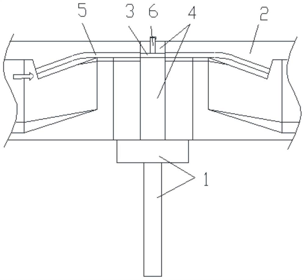
The invention discloses a highway T-beam hogging moment grouting exhaust observation pipe which is applied to a T-beam hogging moment prestressed steel strand laying duct grouting process. A T-beam comprises a bottom bent cap, beam plates erected between adjacent bent caps, grouting pipelines between the two beam plates above the same bent cap, and continuous end pouring pieces filled between twobeam plates above the same bent cap; steel strand laying hole channels are formed in the two ends of each beam plate correspondingly, and the two ends of each grouting pipeline communicate with the corresponding steel strand laying hole channels and are used for steel strand laying and grouting; and the bottom of each observation pipe is fixed to the highest point of the middle of each grouting pipeline, and the top of the observation pipe extends upwards to form a continuous end pouring piece. After the observation pipes are used, the duct grouting time of each span of bridge hogging moment steel strand is shorter than 380 min, and the grouting compactness of the pipeline grouting quality detection result can reach 95% or above.

Description

technical field [0001] The invention relates to the technical field of bridge construction, in particular to a T-beam negative bending moment grouting exhaust observation tube for expressways. Background technique [0002] The purpose of grouting the prestressed steel strands is to prevent the corrosion of the prestressed tendons, and to transfer the prestress to the concrete structure through the condensed slurry, which generally includes the construction of cover beams and pad stones, the erection of beams and slabs, and the connection of pipes , continuous end pouring, steel strand laying and tensioning, steel strand laying channel grouting, observation and anchor sealing. When the traditional negative moment prestressed steel strand laying hole is grouted, the grout is injected from the inlet end to the end of the steel strand laying hole and flows out, which is prone to problems such as not being full and not dense at the highest point. Usually, the quality inspection r...

Claims


Application Information

Patent Timeline
IPC IPC(8): E01D21/00E01D2/00
CPCE01D21/00E01D2/00
Inventor 张明杰魏家旭李明寿尹斌杨凯杨鹏飞姚尧漆海旺孙广林冯金钟马勋令段淑煜罗立宣
Owner YUNNAN CONSTR INVESTMENT HLDG GRP CO LTD
Why Eureka
Eureka Blog
Learn More