Precast beam reinforcement cage component and assembling method thereof

An assembly method and steel cage technology, applied in the direction of building components, structural elements, building reinforcements, etc., can solve the problems of poor reliability, difficult construction, self-heavy PC components, etc., to meet construction requirements, simplify installation procedures, reduce The effect of working at heights

Inactive Publication Date: 2016-09-21
SOUTHEAST UNIV
View PDF5 Cites 11 Cited by
  • Summary
  • Abstract
  • Description
  • Claims
  • Application Information

AI Technical Summary

Problems solved by technology

In order to meet the connection strength requirements of precast concrete components, the reinforcement of the connection nodes is complex and dense, the manual work space is very cramped, the construction is difficult, and the quality and strength of the steel connection are difficult to guarantee, which in turn affects the overall strength and stability of the reinforced concrete structure.
[0005] Existing PC components (full prefabricated reinforced concrete components) are heavy, difficult to transfer, hoist, and locate, and temporary auxiliary support facilities need to be built on site; during the assembly process, the vertical nodes need to be connected by grout anchors, which requires high technical requirements and requires grouting construction techniques. and quality control measures are complex; horizontal joints need to be connected by formwork support cast-in-place, pre-embedded steel plate welding, high-strength bolt connection, etc. The process is complicated, the cost is high, and the reliability is poor. It can only be used after expert argumentation or appraisal organized by relevant departments

Method used


Image

  • Precast beam reinforcement cage component and assembling method thereof
  • Precast beam reinforcement cage component and assembling method thereof
  • Precast beam reinforcement cage component and assembling method thereof

Examples


Embodiment Construction

[0031] The present invention will be further described below in conjunction with embodiment and accompanying drawing.

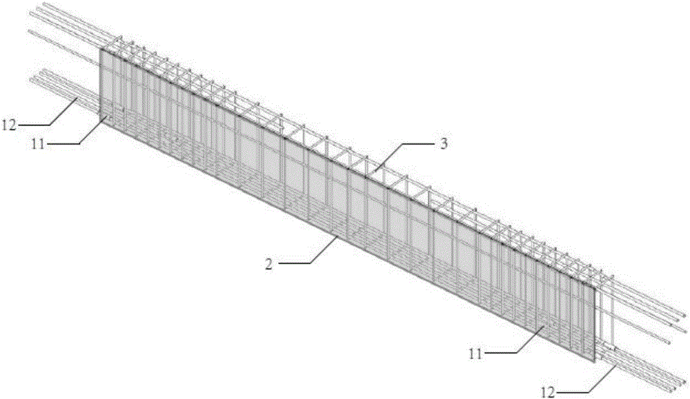
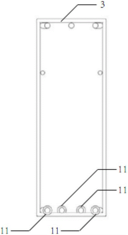
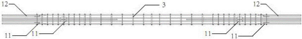
[0032] The prefabricated beam reinforcement cage member of the present invention comprises a steel bar assembly 1, a demolition-free formwork 2 arranged along the front and rear sides and bottom surfaces of the beam, and the demolition-free formwork 2 is connected with the steel bar assembly 1 through a positioning fixture, and the steel bar assembly 1 It is connected by horizontal reinforcement and stirrup. The prefabricated beam reinforcement cage member in the present invention may consist of only one reinforcement assembly 1 or may consist of multiple reinforcement assemblies 1 . Wherein, the dismantling-free formwork 2 adopts a dismantling-free mesh formwork or a dismantling-free formwork, and the positioning and fixing parts adopt connecting ribs or edge frames.

[0033] In one embodiment of the present invention, the following structure is adopted: on...


PUM


Abstract

The invention discloses a precast beam reinforcement cage component and an assembling method thereof. The precast beam reinforcement cage component comprises a reinforcing steel bar assembly and a disassembly-free mould connected with the reinforcing steel bar assembly, wherein the reinforcing steel bar assembly is formed by connecting a horizontal reinforcing bar and a stirrup, and the disassembly-free mould is laid along the front side surface, the rear side surface and the bottom surface of a precast beam and is connected with the reinforcing steel bar assembly into a whole by virtue of a locating fixed part. The precast beam reinforcement cage component has the advantages that a large component and a reinforced concrete large-structure-space civil building can be realized, a working procedure is simplified, high-altitude operation is reduced, and current national reinforced concrete reinforcing bar specification can be met; meanwhile, cost is reduced, locating and supporting precision, assembling efficiency and quality of a structural component are improved, site construction is convenient, and a technology is controllable.

Description

technical field [0001] The invention belongs to the field of construction engineering and relates to a prefabricated beam reinforcement cage component and an assembly method. Background technique [0002] Reinforced concrete structures are widely used due to their advantages of integrity, durability, fire resistance and seismic performance. The existing reinforced concrete structure mainly includes erecting formwork on the construction site, configuring steel bars, and pouring concrete to form an integral reinforced concrete structure, and using prefabricated reinforced concrete components at the factory or construction site, and assembling them into a whole at the site. reinforced-concrete structure. Both methods involve the configuration of steel reinforcement inside the structure or component, and the existing reinforcement technology is mainly divided into two types: [0003] One is that after the formwork is erected on site, the workers use this as a working platform ...

Claims


Application Information

Patent Timeline
Patent Type & Authority Applications(China)
IPC IPC(8): E04C5/06E04G21/14
CPCE04C5/0604E04G21/14
Inventor 张宏张军军刘子洁刘春刘盾吴京冯世虎
Owner SOUTHEAST UNIV
Why Eureka
Try Eureka