Gas back-extraction type water drainage device

A technology of gas and gas pipes, applied in the field of gas back-pumping water discharge devices, which can solve problems such as inability to discharge, accumulation, and reduced area of ​​gas extraction

Pending Publication Date: 2021-03-16
临清市泰宇钻具制造有限公司
View PDF0 Cites 0 Cited by
  • Summary
  • Abstract
  • Description
  • Claims
  • Application Information

AI Technical Summary

Problems solved by technology

[0002] The coal industry usually follows the principle of "pumping first and then mining". The purpose is to discharge the harmful gases contained in the coal seam to avoid safety accidents, such as gas. To achieve the purpose of "pumping first", relatively complete and complicated construction techniques are required. Carry out a series of processes such as detection, drilling, lowering the gas pipe, and sealing the hole. However, during the process of sealing the hole for gas extraction, a large amount of water slag will flow into the gas extraction pipeline due to the high water content in the coal seam, which will lead to gas extraction in the pipeline over time. The reduction of the gas area seriously affects the efficiency of gas drainage and even affects the overall production progress. Under this situation, the mine has purchased or developed many types of pumping and gas pipe drainage devices by itself. Commonly there are positive and negative pressure pumping devices. Through a The simple box body separates water and gas by relying on different densities. A valve body switch is installed at the lower end of the box body. After a period of time, the miner opens the valve to release water. The gas hole cannot be discharged in a short time, and the gas hole will be blocked. In severe cases, the gas pipe will be pressed out of the hole to cause gas leakage. In addition, the cinder free from the box will cause the box to block and accumulate in the gas pipeline, reducing the gas drainage area. , these phenomena are a key to the efficiency of gas drainage

Method used


Image

  • Gas back-extraction type water drainage device
  • Gas back-extraction type water drainage device
  • Gas back-extraction type water drainage device

Examples


Embodiment Construction

[0014] With reference to the figures covered in the accompanying drawings and specific practical instructions are as follows:

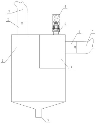
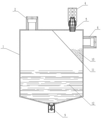
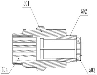
[0015] As shown in the figure, a gas reverse pumping type water release device is composed of three parts: a storage box 1, a safety valve group 5, and an automatic discharge valve group 9. A drilled gas pipe connector 6 is installed on one side of the storage box 1 , the drilled gas pipe connector 6 can be connected with one or more drilled gas pipes 7, the upper side of the storage box 1 is provided with a roadway gas pipe connector 2, and through the roadway gas pipe connector 2 and the roadway gas pipe 3 To connect, a slag-water separation mechanism 11 is installed in the storage box 1, and the cinder 10 and water 12 are separated through the slag-water separation mechanism 11. When the cinder 10 accumulates for a certain period of time, the cinder 10 can be cleaned out through the side opening plate 8. Storage box 1.

[0016] According to the ab...


PUM


Abstract

The invention mainly provides a gas back-extraction type water drainage device. The device is mainly used for roadways which contain water in coal seams and need to be drained in the gas water drainage process, and mainly comprises a storage box body, a safety valve group, and an automatic water drainage valve group. Coal slag and water are separated through a slag-water separation mechanism, meanwhile, the flow velocity resistance of water is increased to separate water from gas, the water falls into the bottom of the storage box body according to the gravity principle of the water, and the gas forms negative pressure in the storage box body under the extraction action of a roadway gas pipe and is extracted into the roadway gas pipe, so that coal slag is prevented from entering into the roadway gas pipe to cause blockage of a gas pipe; and by separating the water, the slag and the gas, the trouble of manual water water drainage of miners can be effectively eliminated, the coal slag isprevented from blocking the gas pipe and flowing into the box body to be mixed with water to cause blockage of a water drainer, the gas extraction efficiency is greatly improved, and the coal mine production period is shortened by 2-3 times.

Description

technical field [0001] The invention mainly relates to a gas reverse pumping type water discharge device, which is mainly used for water-containing coal seams and drainage tunnels are required during the gas pumping process. Background technique [0002] The coal industry usually follows the principle of "pumping first and then mining". The purpose is to discharge the harmful gases contained in the coal seam to avoid safety accidents, such as gas. To achieve the purpose of "pumping first", relatively complete and complicated construction techniques are required. Carry out a series of processes such as detection, drilling, lowering the gas pipe, and sealing the hole. However, during the process of sealing the hole for gas extraction, a large amount of water slag will flow into the gas extraction pipeline due to the high water content in the coal seam, which will lead to gas extraction in the pipeline over time. The reduction of the gas area seriously affects the efficiency of...

Claims


Application Information

Patent Timeline
Patent Type & Authority Applications(China)
IPC IPC(8): E21F16/00E21F7/00
CPCE21F7/00E21F16/00
Inventor 郑遵芹刘跃伟
Owner 临清市泰宇钻具制造有限公司
Why Eureka
Try Eureka