Twisting type water power machine

A technology of power machine and water channel, applied in the field of twisting water power machine, can solve problems such as environmental pollution, inconvenience, and speed up the consumption of limited oil resources, and achieve the effects of high transmission efficiency, resource saving, and simple use

Pending Publication Date: 2021-03-16
王建设
View PDF9 Cites 0 Cited by
  • Summary
  • Abstract
  • Description
  • Claims
  • Application Information

AI Technical Summary

Problems solved by technology

[0002] At present, the operation of the power machine is mostly fuel oil and combustible gas as energy sources, and the fuel oil and combustible gas are all extracted from petroleum. The consumption of petroleum resources, at the same time, the operation of the power machine will also discharge harmful gases to humans and nature, causing environmental pollution
So people began to study power machines that use water as energy. Most people still use the head of flowing water to convert the potential energy of water flow into mechanical energy through water turbines, and can also convert mechanical energy into electrical energy, such as the application of power stations; they rarely use water flow energy. It is converted into mechanical energy, such as an invention whose application number is CN01216218.3, and its name is "rotary scrubbing and scrubbing device driven by water power". The reaction force of the guide rail to the plunger makes it return, and uses the component force of this force to make it rotate, thereby partially rotating the nozzle, but this implementation method does not fully utilize the energy of the water flow, and the reciprocating motion of the plunger The friction force in the water is relatively large, and it needs high water pressure to drive. It cannot be driven by ordinary tap water, which is still inconvenient.

Method used


Image

  • Twisting type water power machine
  • Twisting type water power machine
  • Twisting type water power machine

Examples


Embodiment Construction

[0034] Embodiments of the present invention are described in detail below, examples of which are shown in the drawings, wherein the same or similar reference numerals designate the same or similar elements or elements having the same or similar functions throughout. The embodiments described below by referring to the figures are exemplary and are intended to explain the present invention and should not be construed as limiting the present invention.

[0035] The present invention will be further described below in conjunction with the accompanying drawings and specific embodiments.

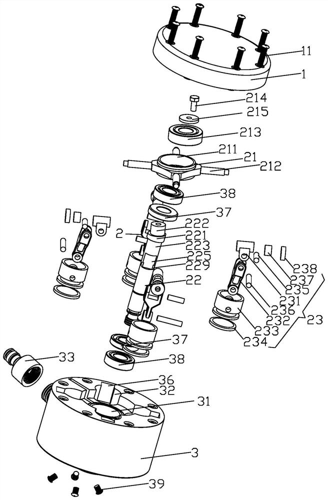
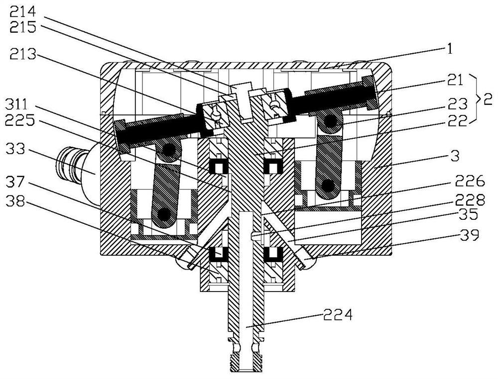
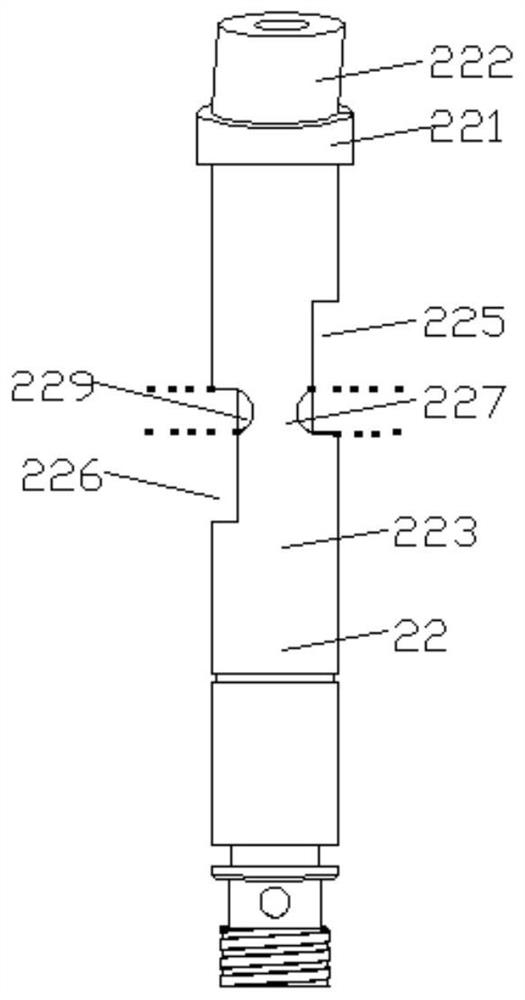
[0036] see Figure 1 to Figure 6 As shown, a twisting type hydrodynamic machine includes an upper cover 1, a twisting mechanism 2 and a lower cylinder base 3, and the upper cover 1 is fixed on the lower cylinder base 3 by long screws 11, and the twisting mechanism 2 is arranged inside the lower cylinder base 3, the upper cover 1 is designed according to the structure of the lower cylinder base 3,...


PUM


Abstract

The invention provides a twisting type water power machine which comprises an upper cover, a twisting mechanism and a lower cylinder base. The upper cover is fixed to the lower cylinder base through along screw, the twisting mechanism is arranged in the lower cylinder base, a stepped rotating shaft hole is formed in the middle of the lower cylinder base, and piston inner cavities are evenly formed in the periphery of the rotating shaft hole; a water inlet nozzle is connected to the outer side of the lower cylinder base and arranged between two of piston inner cavities; and the twisting mechanism comprises a twisting support, a rotating shaft and a piston assembly. According to the twisting type water power machine, flowing energy of tap water can be directly used for driving pistons to dowork, then the rotating shaft is driven to rotate, the transmission efficiency is high, resources are saved, and the twisting type water power machine is simple to use and convenient to operate, andcan be widely applied to different cleaners.

Description

technical field [0001] The invention relates to the technical field of power equipment, in particular to a twisting type hydrodynamic machine. Background technique [0002] At present, the operation of the power machine is mostly fuel oil and combustible gas as energy sources, and the fuel oil and combustible gas are all extracted from petroleum. At the same time, the operation of the power machine will also discharge harmful gases to humans and nature, causing environmental pollution. So people began to study power machines that use water as energy. Most people still use the head of flowing water to convert the potential energy of water flow into mechanical energy through water turbines, and can also convert mechanical energy into electrical energy, such as the application of power stations; they rarely use water flow energy. It is converted into mechanical energy, such as an invention whose application number is CN01216218.3, and its name is "rotary scrubbing and scrubbin...

Claims


Application Information

Patent Timeline
Patent Type & Authority Applications(China)
IPC IPC(8): F03C1/06
CPCF03C1/0613F03C1/0623
Inventor 王建设王恒聪
Owner 王建设
Why Eureka
Try Eureka