Infusion pump used for non-contact automatic hand sterilizer

A non-contact, pumping pump technology, applied in rotary piston/oscillating piston pump components, rotary piston/oscillating piston pump combinations, machines/engines, etc. The pumping pump has a complex structure and low manufacturing precision requirements.

Pending Publication Date: 2021-03-16
上海荣安五金机电有限公司
View PDF0 Cites 1 Cited by
  • Summary
  • Abstract
  • Description
  • Claims
  • Application Information

AI Technical Summary

Problems solved by technology

[0005] In order to overcome the problems existing in the related technology to a certain extent, the purpose of this application is to provide a liquid suction pump for a non-contact automatic hand sanitizer, which has a simple structure, low manufacturing accuracy requirements, and is easy to process; Lubricate the inside of the pump, and the wear is very small; and the seal between the rotating part and the fixed part can be directly completed by the disinfectant seal; the work is stable and reliable, the operation is simple, and the maintenance is convenient; it can solve the problem of the existing automatic disinfection machine. The structure of the liquid pump is complex, the friction loss between parts is large, and it is impossible to reverse the suction nozzle and the residual liquid in the pipeline after the liquid suction is completed, resulting in the problem of inertial spraying

Method used


Image

  • Infusion pump used for non-contact automatic hand sterilizer
  • Infusion pump used for non-contact automatic hand sterilizer
  • Infusion pump used for non-contact automatic hand sterilizer

Examples


Embodiment Construction

[0039] Exemplary embodiments will be described in detail herein, examples of which are illustrated in the accompanying drawings. Where the following description refers to the drawings, the same numerals in different drawings refer to the same or similar elements unless otherwise indicated. The implementations described in the illustrative examples below are not intended to represent all implementations consistent with this application. Rather, they are merely examples of means consistent with some aspects of the present application as recited in the appended claims.

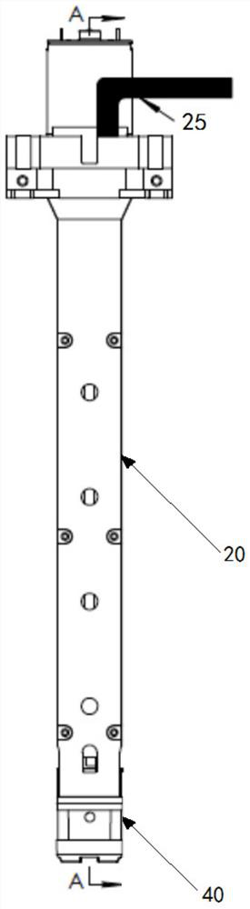
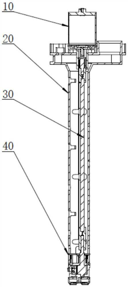
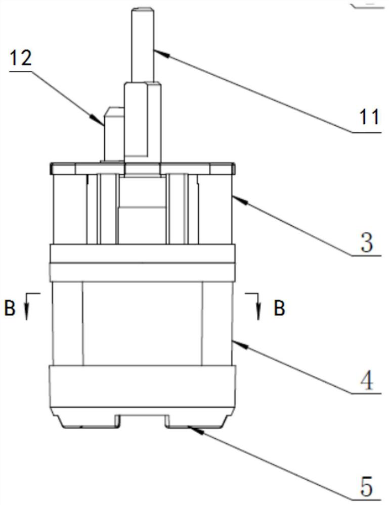
[0040] refer to Figure 1 to Figure 16 , this specific embodiment provides a liquid suction pump for a non-contact automatic hand sterilizer, including a liquid suction pump pump body, and the liquid suction pump pump body includes a casing 20, a liquid discharge pipe 25, and a pump body 40 and driving device, the pump body 40 includes a chamber cover 3, a pump body chamber 4, an eccentric cam 2 and a blocking as...


PUM

PropertyMeasurementUnit
Heightaaaaaaaaaa
Diameteraaaaaaaaaa

Abstract

The invention discloses an infusion pump used for a non-contact automatic hand sterilizer. The infusion pump comprises an infusion pump body, the infusion pump body comprises a shell, a liquid discharging pipe, a pump body and a driving device, the pump body comprises a pump body cavity, an eccentric cam and a blocking assembly, the pump body cavity comprises a liquid inlet cavity and a liquid outlet cavity, the liquid outlet cavity of the pump body cavity communicates with the liquid discharging pipe, and a liquid inlet is arranged at the lower end of the pump body cavity. When the driving device drives the eccentric cam to rotate in the first direction, the volume of the liquid inlet cavity is increased, liquid enters the liquid inlet cavity, the volume of the liquid outlet cavity is reduced, and the liquid in the liquid outlet cavity is discharged into the liquid discharging pipe. When the driving device drives the eccentric cam to rotate in the second direction, the volume of the liquid outlet cavity is increased, liquid in the liquid discharging pipe flows into the liquid outlet cavity, the volume of the liquid inlet cavity is reduced, and the liquid in the liquid inlet cavityis discharged from the liquid inlet. According to the infusion pump, the driving device controls the eccentric cam to rotate so that liquid suction and discharging can be directly completed, inversion can be conducted after liquid suction is completed so that liquid can be sucked back, the structure is simple, and reliability is high.

Description

technical field [0001] The present application relates to the technical field of accessories for automatic hand sterilizers, and more particularly, to a liquid pump for non-contact automatic hand sterilizers. Background technique [0002] The struggle between human beings and viruses and bacteria has started since the birth of human beings. Due to the epidemic of coronaviruses, the spread of human-to-human transmission through the air has become more dangerous and difficult to control. The general characteristics of these viruses are transmission. Strong ability, there is a common phenomenon of human-to-human transmission, mainly spread by droplets, and contact with public objects (hands touching eyes and nose, etc.). Therefore, in order to block the spread, reduce the number of infected people, and complete self-protection, it is very important to disinfect the hand, which is the key part of the infection. Therefore, in the sanitation management of a wide range of industri...

Claims


Application Information

Patent Timeline
IPC IPC(8): F04C11/00F04C13/00F04C15/06F04C15/00A61L2/18
CPCF04C11/008F04C13/00F04C15/06F04C15/0003A61L2/18
Inventor 竺国荣
Owner 上海荣安五金机电有限公司
Why Eureka
Try Eureka