Lifting type water-adjusting variable valve

A variable, valve technology, applied in the direction of sliding valve, valve details, valve device, etc., can solve the problems of water volume adjustment, poor control accuracy, affecting valve use, valve sealing and leak-proof performance problems, etc., to achieve good water volume control. effect, improving leak-proof sealing, improving sealing and leak-proofing effect

Inactive Publication Date: 2021-03-16
西安致开工业自动化工程有限公司
View PDF3 Cites 0 Cited by
  • Summary
  • Abstract
  • Description
  • Claims
  • Application Information

AI Technical Summary

Problems solved by technology

[0002] Valve is a kind of pipeline connector, which has multiple functions such as controlling pipeline switch and controlling flow direction. There are many kinds of valves with different functions, which provide many conveniences for life and industry. However, the existing public patents CN104633150A, CN210830701U, The valve in CN210344495U has drawbacks in the use process, the adjustment and control accuracy of the water volume is not good, and there are problems in the sealing and leak-proof performance of the valve, which affects the use of the valve. For this reason, we propose a lifting type water adjustment can variable valve

Method used


Image

  • Lifting type water-adjusting variable valve
  • Lifting type water-adjusting variable valve
  • Lifting type water-adjusting variable valve

Examples


Embodiment 1

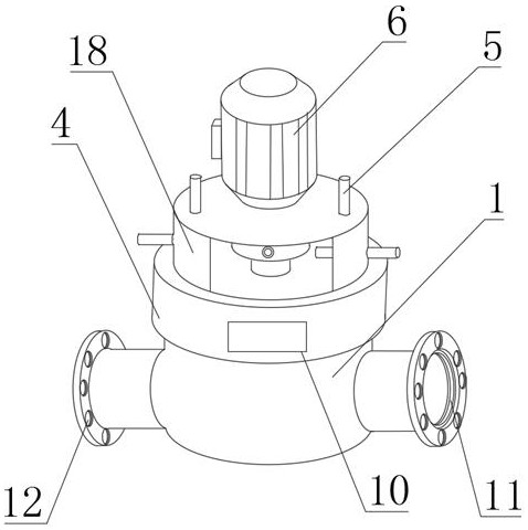
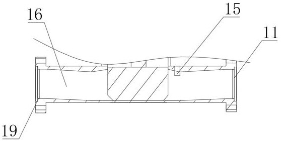
[0021] Example 1 as figure 1 As shown, a pull-type variable water adjustment valve includes a valve main body 1, the right end of the valve main body 1 is provided with a water inlet 2, the left end of the valve main body 1 is provided with a water outlet 3, and the inside of the valve main body 1 is provided with a movable chamber 17. A valve core 14 is provided inside the movable chamber 17, a connecting seat 4 is provided on the upper surface of the valve main body 1, a motor seat 18 is provided on the upper surface of the connecting seat 4, a servo motor 6 is provided on the upper surface of the motor seat 18, and the servo motor The port of 6 is positioned at the top lower end place of motor seat 18 and is provided with shaft coupling 7, and just below shaft coupling 7 is provided with valve stem 9, and the upper surface edge of motor seat 18 and both sides are all provided with positioning rod 5.

Embodiment 2

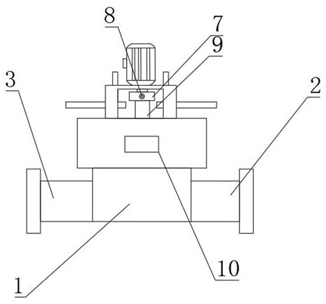
[0022] Embodiment 2 is on the basis of embodiment 1, as figure 2 , 3 As shown, the motor seat 18 is flexibly connected to the servo motor 6, and the valve stem 9 is flexibly connected to the coupling 7. The valve stem 9 extends through the connecting seat 4 to the inside of the valve main body 1 and is connected to the valve core 14. The valve stem 9 and the spool 14 are flexibly connected, which is beneficial to the pulling movement of the spool 14. The positioning rod 5 extends through the motor seat 18 to the inside, and the positioning rod 5 and the motor seat 18 are flexibly connected. The positioning rod 5 The number is several groups, and the front end surface of the coupling 7 is provided with a position sensor 8, and the position sensor 8 and the coupling 7 are flexibly connected, which is beneficial to the fixing and monitoring of the position.

Embodiment 3

[0023] Embodiment 3 is on the basis of embodiment 1, as figure 1 and 3 As shown, the front surface of the connection seat 4 is provided with a flow indicator 10, the flow indicator 10 and the connection seat 4 are flexibly connected, the valve main body 1 is provided with a flow sensing probe 15, and the flow sensing probe 15 and the valve main body 1 are The movable connection is electrically connected between the flow sensor and the flow sensing probe 15, which is beneficial to the control of the water volume.


PUM


Abstract

The invention discloses a lifting type water-adjusting variable valve. The lifting type water-adjusting variable valve comprises a valve body, wherein a water inlet is formed in the right end of the valve body; a water outlet is formed in the left end of the valve body; a movable cavity is formed in the valve body; a valve element is arranged in the movable cavity; a connecting base is arranged onthe surface of the upper end of the valve body; a motor base is arranged on the surface of the upper end of the connecting base; a servo motor is arranged on the surface of the upper end of the motorbase; a coupling is arranged at the position, located at the lower end of the top of the motor base, of a port of the servo motor; a valve rod is arranged under the coupling; and positioning rods arearranged on the edge and the two sides of the surface of the upper end of the motor base. The lifting type water-adjusting variable valve has the good water amount control effect, the control precision is high, meanwhile, the good sealing and leakage-proof effects are achieved, and water loss and waste are reduced.

Description

technical field [0001] The invention relates to the technical field of valve equipment, in particular to a pull-type variable water adjustment valve. Background technique [0002] Valve is a kind of pipeline connector, which has multiple functions such as controlling pipeline switch and controlling flow direction. There are many kinds of valves with different functions, which provide many conveniences for life and industry. However, the existing public patents CN104633150A, CN210830701U, The valve in CN210344495U has drawbacks in the use process, the adjustment and control accuracy of the water volume is not good, and there are problems in the sealing and leak-proof performance of the valve, which affects the use of the valve. For this reason, we propose a lifting type water adjustment can Change the valve. Contents of the invention [0003] The main purpose of the present invention is to provide a pull-type variable water adjustment valve, which can effectively solve the...

Claims


Application Information

Patent Timeline
Patent Type & Authority Applications(China)
IPC IPC(8): F16K3/30F16K3/314F16K27/04F16K31/04F16K37/00F16K41/10
CPCF16K3/30F16K3/314F16K27/04F16K31/04F16K37/0041F16K37/005F16K41/10
Inventor 黄政普
Owner 西安致开工业自动化工程有限公司
Why Eureka
Try Eureka