
Distributed collaborative debugging method and system for industrial robot

A technology of industrial robots and debugging methods, applied in transmission systems, digital transmission systems, instruments, etc., can solve the problem of distinguishing data from different collaborative development nodes, cannot solve the problem of concurrent debugging of multiple collaborative development nodes, and cannot distinguish between multiple industrial Problems such as robot resources and collaborative development node related information can achieve the effect of shielding differences and debugging type differences

Active Publication Date: 2021-03-16
716TH RES INST OF CHINA SHIPBUILDING INDAL CORP
View PDF8 Cites 2 Cited by
  • Summary
  • Abstract
  • Description
  • Claims
  • Application Information

AI Technical Summary

Problems solved by technology

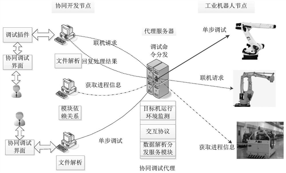
[0003] The current debugging method can solve the problem of debugging a single development node to a single industrial robot, but this debugging model cannot solve the problem of concurrent debugging of multiple collaborative development nodes; the debugging agent can have certain perception capabilities, such as the access and request of collaborative nodes, etc. , but for the concurrent debugging tasks of multiple collaborative development nodes, the data of different collaborative development nodes cannot be distinguished and processed, and the access to shared resources cannot be arbitrated. At the same time, the debugging agent cannot distinguish between multiple industrial robot resources and collaborative development nodes. Therefore, it is necessary to build a collaborative debugging agent to automatically assign an ID, a unique port number, and set permissions for each collaborative development node, and dynamically adjust it according to the target resource for debugging, so as to realize concurrent debugging of multiple collaborative nodes. Then realize the collaborative debugging function of industrial robots under limited resources

Method used


Image

  • Distributed collaborative debugging method and system for industrial robot
  • Distributed collaborative debugging method and system for industrial robot

Examples


Embodiment Construction

[0035] In order to make the purpose, technical solutions and advantages of the present application more clearly understood, the present application will be described in further detail below with reference to the accompanying drawings and embodiments. It should be understood that the specific embodiments described herein are only used to explain the present application, but not to limit the present application.

[0036] In addition, if there are descriptions involving "first", "second", etc. in the embodiments of the present invention, the descriptions of "first", "second", etc. are only used for the purpose of description, and should not be construed as indicating or implying Its relative importance or implicitly indicates the number of technical features indicated. Thus, a feature delimited with "first", "second" may expressly or implicitly include at least one of that feature. In addition, the technical solutions between the various embodiments can be combined with each oth...


PUM


Abstract

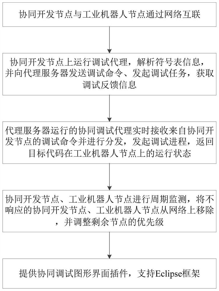
The invention discloses a distributed collaborative debugging method and system for an industrial robot. The method comprises the steps that collaborative development nodes and industrial robot nodesare interconnected; a debugging agent is run on the collaborative development node, the symbol table information is analyzed, a debugging command and a debugging task are sent to a proxy server, and feedback information is obtained; a collaborative debugging agent operated by the proxy server receives and distributes a debugging command from the collaborative development node, initiates a debugging process, and returns an operation state of the target code on the industrial robot node; and the nodes which do not respond are removed, and the priorities of the remaining nodes are adjusted. According to the method and system, the problems of debugging task suspension, conflict and even interruption caused by resource sharing and mutual exclusion can be solved, differences of bottom software and hardware platforms of the industrial robots and debugging type differences are shielded, unified debugging interface styles and operations are achieved, collaborative debugging in a distributed multi-industrial-robot collaborative scene can be achieved, the application development period is shortened, and the product competitiveness of the robot industry in China is improved.

Description

technical field [0001] The invention belongs to the field of software development collaborative debugging, in particular to a distributed collaborative debugging method and system for industrial robots. Background technique [0002] At present, the application scenarios of distributed industrial robots are becoming more and more complex, and the scale of software is getting larger and larger. In an application scenario, there are industrial robots from multiple manufacturers to complete application tasks together. Therefore, during development and debugging, multiple collaborations are required. The development node performs collaborative debugging of multiple industrial robots at the same time. While multiple collaborative development nodes are concurrently debugged, the collaborative development node robot application needs to access the shared or mutually exclusive resources of the industrial robot controller, which may cause debugging task suspension, conflict or even in...

Claims


Application Information

Patent Timeline
Patent Type & Authority Applications(China)
IPC IPC(8): G06F9/50H04L12/26H04L29/08
CPCG06F9/5027H04L67/10H04L67/12H04L43/10H04L67/56Y02P90/02
Inventor 孙志宏孔祥营张大方胡先浪倪佳炜
Owner 716TH RES INST OF CHINA SHIPBUILDING INDAL CORP
Learn More