Clamping device for television display screen detection

A technology of clamping device and display screen, which is applied in the field of television, can solve the problems of increased detection cost, increased production loss, increased production cost, etc., and achieves the effects of convenient operation, improved efficiency, and time saving

Inactive Publication Date: 2021-03-19
南京樊冠商贸有限公司
View PDF0 Cites 0 Cited by
  • Summary
  • Abstract
  • Description
  • Claims
  • Application Information

AI Technical Summary

Problems solved by technology

[0002] With the improvement of living standards, televisions have become an indispensable household appliance in our lives. In the manufacturing process of televisions, display screens play an extremely important role, and the quality inspection of screens is particularly important. Usually, the screen to be tested is fixed by placing the display screen in the fixing slot, and then it is tested. The size of the fixing slot is often set, and only screens that match its specifications can be placed, which requires testing. According to different screen sizes, a variety of fixtures are set up, resulting in an increase in production costs
[0003] At the same time, even if it is an adapted fixing slot and screen, the fixing slot is often slightly larger than the size of the screen to facilitate the insertion and removal of the screen. In the process, it is easy to be bumped and damaged, which increases the loss of production and increases the cost of inspection. Therefore, we propose a clamping device for TV display screen inspection to solve the above problems, which can be used for display screens of different sizes. Automatic clamping and fixing reduces the friction and collision between the screen and the fixing groove, avoids loss, reduces the cost of production and maintenance, is convenient to operate, saves time, and improves the efficiency of detection

Method used


Image

  • Clamping device for television display screen detection
  • Clamping device for television display screen detection
  • Clamping device for television display screen detection

Examples


Embodiment Construction

[0023] The following will clearly and completely describe the technical solutions in the embodiments of the present invention with reference to the accompanying drawings in the embodiments of the present invention. Obviously, the described embodiments are only some, not all, embodiments of the present invention. Based on the embodiments of the present invention, all other embodiments obtained by persons of ordinary skill in the art without making creative efforts belong to the protection scope of the present invention.

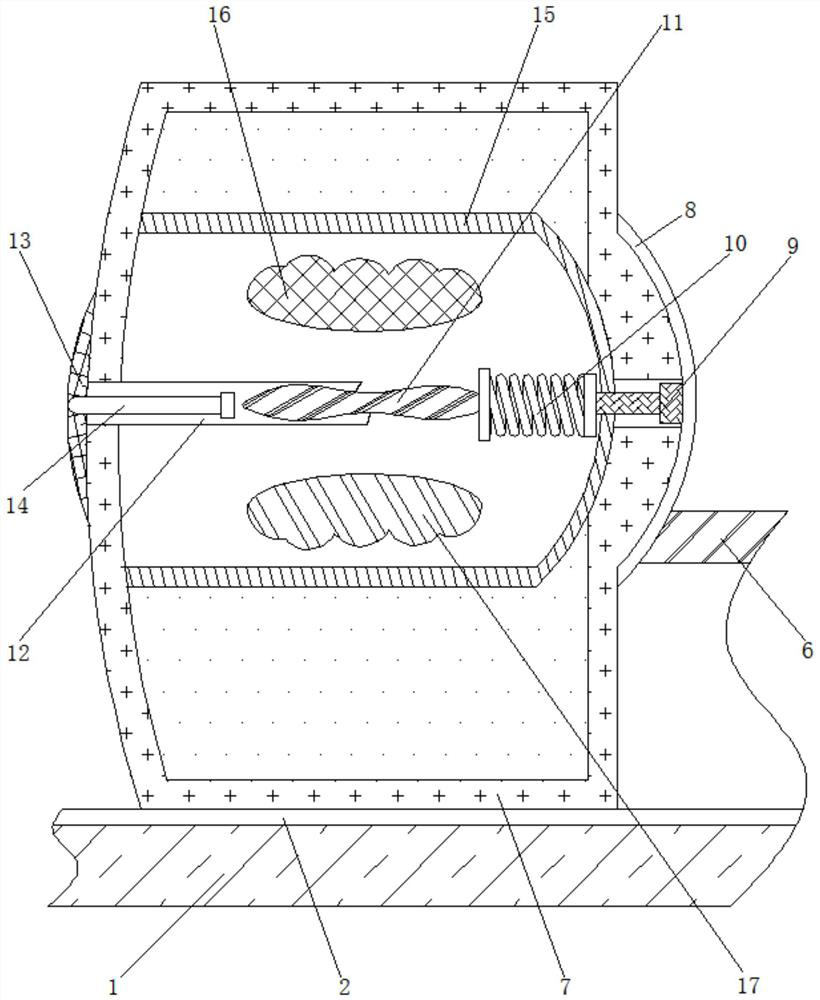
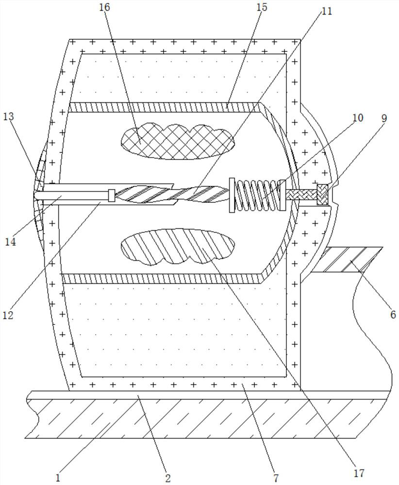
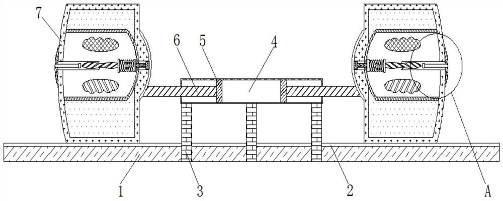
[0024] see Figure 1-4 , a clamping device for TV display screen detection, comprising a base 1, the top of the base 1 is provided with a movable groove 2, the top of the base 1 is fixedly connected with a support column 3, there are three support columns 3, and three support columns 3 Both are perpendicular to the base 1, the top of the supporting column 3 is movably connected with a placement plate 4, the inside of the placement plate 4 is movably connected ...


PUM


Abstract

The invention relates to the technical field of televisions, and discloses a clamping device for television display screen detection. The device comprises a base, wherein a movable groove is formed inthe top of the base, a supporting column is fixedly connected to the top of the base, a placement plate is movably connected to the top of the supporting column, a piston is movably connected to theinterior of the placement plate, the outer side of the piston is movably connected to a movable rod, the outer side of the movable rod is movably connected to a moving device, and the inner side of the moving device is movably connected to a contact block. According to the clamping device for television display screen detection, through the characteristics of an electrorheological fluid, when a dielectric plate moves towards the outer side, a current is generated between a positive plate and a negative plate, so that the electrorheological fluid is converted from liquid to solid, a display screen on the inner side is fixed, friction and collision between the screen and a fixing groove are reduced, loss is avoided, the production and maintenance cost is reduced, the operation is convenient,the time is saved, and the detection efficiency is improved.

Description

technical field [0001] The invention relates to the technical field of televisions, in particular to a clamping device for testing a television display screen. Background technique [0002] With the improvement of living standards, televisions have become an indispensable household appliance in our lives. In the manufacturing process of televisions, display screens play an extremely important role, and the quality inspection of screens is particularly important. Usually, the screen to be tested is fixed by placing the display screen in the fixing slot, and then it is tested. The size of the fixing slot is often set, and only screens that match its specifications can be placed, which requires testing during testing. Fixing devices of various specifications are provided according to different screen sizes, resulting in increased production costs. [0003] At the same time, even if it is an adapted fixing slot and screen, the fixing slot is often slightly larger than the size ...

Claims


Application Information

Patent Timeline
Patent Type & Authority Applications(China)
IPC IPC(8): B25B11/00
CPCB25B11/00
Inventor 吕冠霖
Owner 南京樊冠商贸有限公司
Why Eureka
Try Eureka