Multifunctional high-efficiency die-cutting machine

A high-efficiency, die-cutting machine technology, applied in the direction of metal processing, etc., can solve the problems of reducing cleaning efficiency, time-consuming and laborious, and affecting the normal use of die-cutting machines, so as to improve cleaning efficiency, improve film cutting accuracy, and increase finished products. The effect of the transport function

Pending Publication Date: 2021-03-19
兆均精工科技(苏州)有限公司
View PDF0 Cites 3 Cited by
  • Summary
  • Abstract
  • Description
  • Claims
  • Application Information

AI Technical Summary

Problems solved by technology

[0003] During the use of the traditional die-cutting machine, a large amount of waste and residual glue are likely to be generated when the material is cut, and a lot of fine debris will accumulate on the cutter, which will seriously affect the normal use of the die-cutting machine over time. Ordinary waste cleaning devices need to be cleaned manually, which is time-consuming and labor-intensive, reduces the efficiency of cleaning, consumes manpower and material resources, and has a lot of troubles

Method used


Image

  • Multifunctional high-efficiency die-cutting machine
  • Multifunctional high-efficiency die-cutting machine
  • Multifunctional high-efficiency die-cutting machine

Examples


Embodiment Construction

[0022] In order to make the technical means, creative features, goals and effects achieved by the present invention easy to understand, the present invention will be further described below in conjunction with specific embodiments.

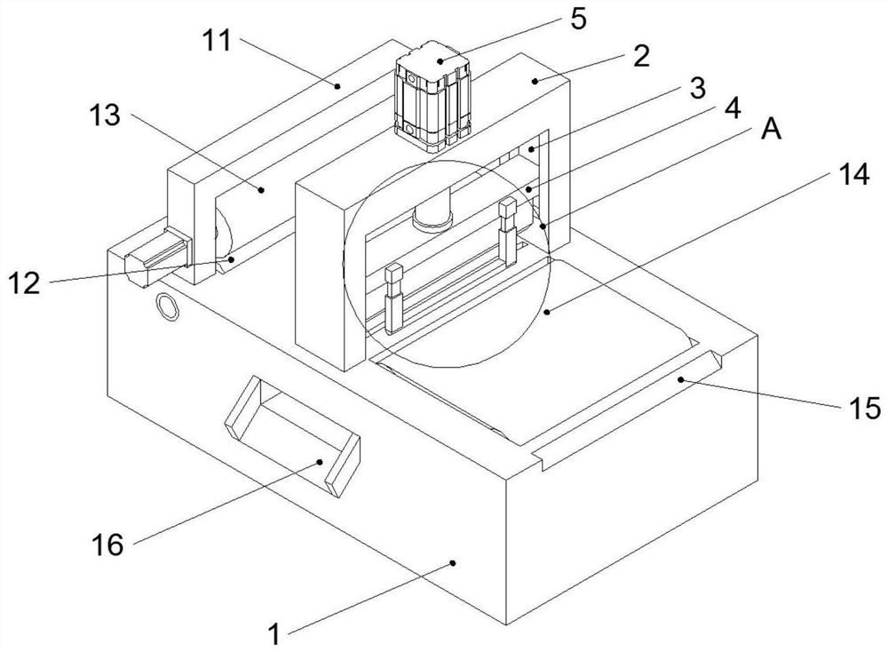
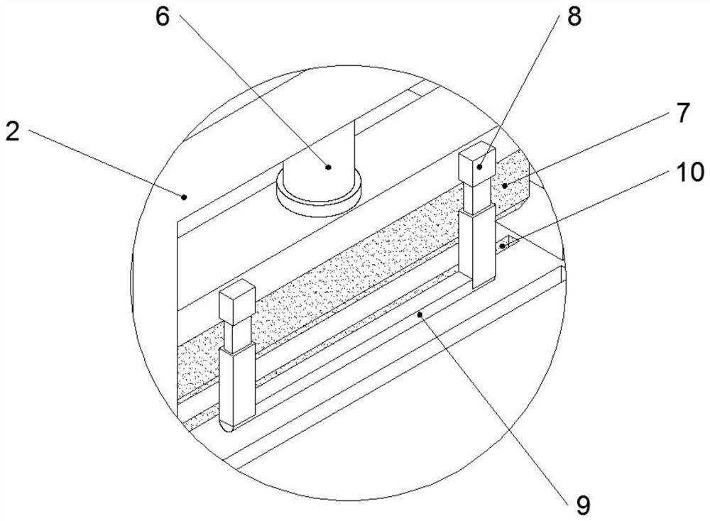
[0023] Such as Figure 1-5 As shown, a multifunctional and high-efficiency die-cutting machine of the present invention includes a machine platform 1, a die-cutting frame 2 is fixed in the middle of the top of the machine platform 1, and a chute 3 is fixedly provided at both ends of the inner side of the die-cutting frame 2. The inner side of the chute 3 is slidingly connected to the cutter seat 4, the top middle part of the die-cutting frame 2 is fixedly provided with a pneumatic cylinder 5, the top middle part of the die-cutting frame 2 is provided with an air pressure rod 6, and the top end of the cutter seat 4 is fixedly provided with a cutting cylinder 5. Knife 7, the both sides of cutter seat 4 are fixedly connected telescopic frame 8, and t...


PUM


Abstract

The invention discloses a multifunctional high-efficiency die-cutting machine which comprises a machine table. A die-cutting frame is fixedly arranged in the middle of the top end of the machine table, sliding grooves are fixedly formed in the two ends of the inner side of the die-cutting frame, a cutter base is slidably connected to the inner sides of the sliding grooves, and a pneumatic cylinderis fixedly arranged in the middle of the top end of the die-cutting frame. A cutter is fixedly arranged at the top end of the cutter base, telescopic frames are fixedly connected to the two sides ofthe cutter base, lower pressing rods are fixedly arranged at the bottom ends of the telescopic frames, and a cutter groove is formed in the position, corresponding to the middle of the cutter, of themiddle of the top end of the machine table in a penetrating manner. A pressing roller frame is fixedly arranged on one side of the top end of the machine table, a lower pressing roller is rotatably connected to the position, corresponding to the pressing roller frame, of the top end of the machine table through bearings, and an upper pressing roller is rotatably connected to the middle of the pressing roller frame through bearings. A finished product conveying belt is fixedly arranged on the other side of the top end of the machine table, and a finished product discharging port is fixedly formed in the other side of the top of the machine table. The multifunctional high-efficiency die-cutting machine is simple and reasonable in structure and novel in design, and has higher multifunctionaluse efficiency in use of die-cutting machines.

Description

technical field [0001] The invention relates to the technical field of die-cutting machines, in particular to a multi-functional and high-efficiency die-cutting machine. Background technique [0002] Die Cutting Machine (Die Cutting Machine) is also called beer machine, cutting machine, CNC stamping machine, mainly used for some corresponding non-metallic materials, stickers, EVA, double-sided tape, electronics, mobile phone pads, printing paper, etc. Die-cutting (full-cut, half-cut), indentation and bronzing operations, lamination, automatic waste discharge, die-cutting machines use steel knives, metal molds, steel wires (or templates carved from steel plates), and apply them through embossing plates With a certain pressure, the printed matter or cardboard is rolled and cut into a certain shape. [0003] During the use of the traditional die-cutting machine, a large amount of waste and residual glue are likely to be generated when the material is cut, and a lot of fine deb...

Claims


Application Information

Patent Timeline
Patent Type & Authority Applications(China)
IPC IPC(8): B26D1/08B26D7/08B26D7/02B26D7/32B26D7/27
CPCB26D1/085B26D7/025B26D7/088B26D7/27B26D7/32
Inventor 徐军
Owner 兆均精工科技(苏州)有限公司
Why Eureka
Try Eureka