
Road and bridge scribing device

A scribing device and bridge technology, which is applied in the direction of roads, roads, road repairs, etc., can solve the problem of poor bonding between the scribing paint and the ground, and achieve the effects of reducing adhesion on the ground, improving cleaning, and increasing service life

Inactive Publication Date: 2021-03-19
邓聪
View PDF0 Cites 1 Cited by
  • Summary
  • Abstract
  • Description
  • Claims
  • Application Information

AI Technical Summary

Problems solved by technology

[0004] The purpose of the present invention is to solve the problem of poor adhesion between the marking paint and the ground in the prior art, and propose a road bridge marking device

Method used


Image

  • Road and bridge scribing device
  • Road and bridge scribing device
  • Road and bridge scribing device

Examples


Embodiment 1

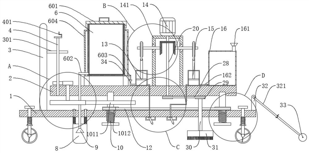
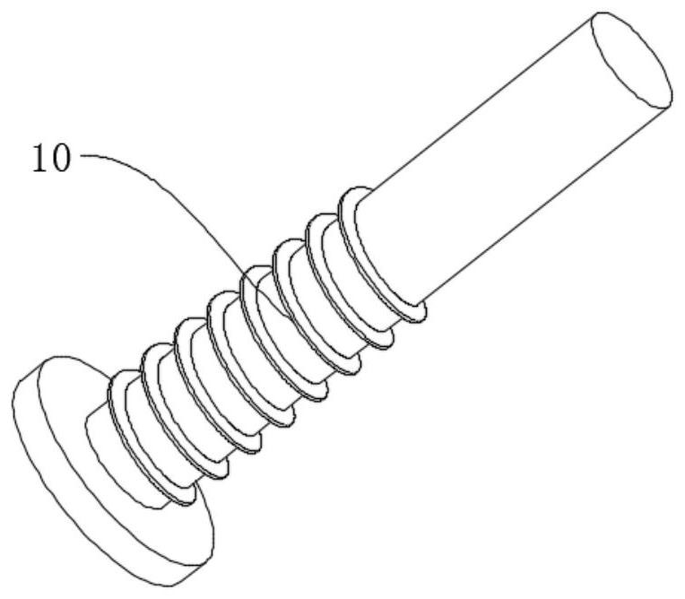
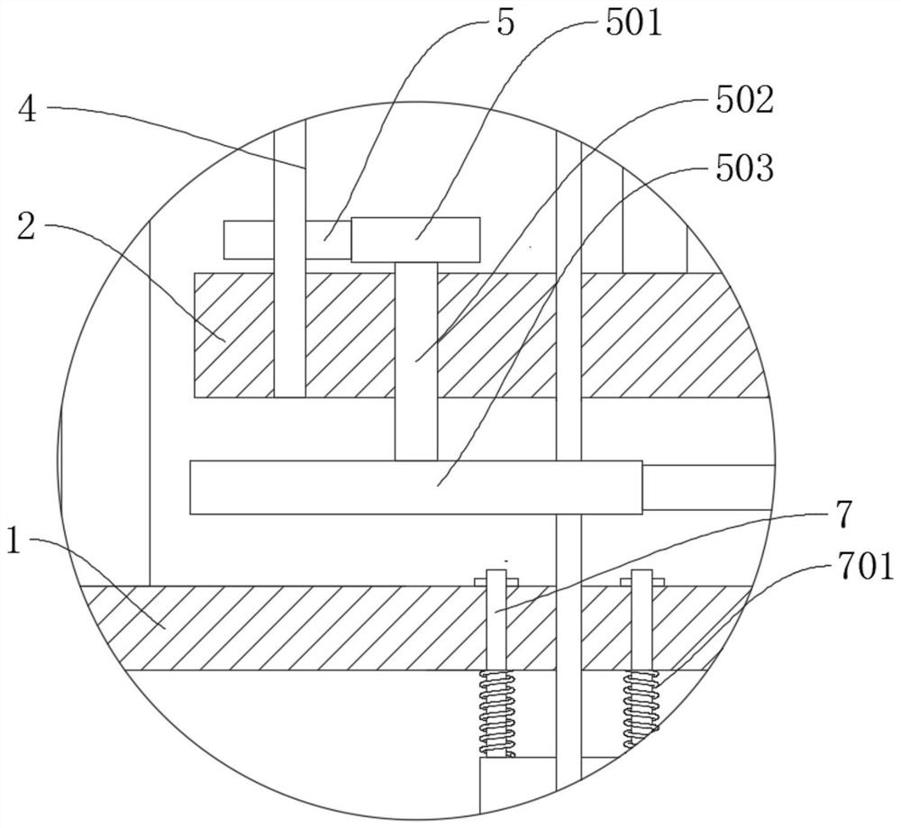
[0032] refer to Figure 1-6 , a road bridge marking device, comprising a base 1 and a support plate 2, a threaded rod 10 is connected between the base 1 and the support plate 2, a lifting mechanism is fixedly connected to the threaded rod 10, and a heating cylinder is fixedly connected to the support plate 2 6. The first cylinder 13, the fixed frame 141 and the second cylinder 15, the fixed frame 141 is fixedly connected with the motor 14, the output end of the motor 14 is fixedly connected with the rotating shaft 20, and the rotating shaft 20 is fixedly connected with the first bevel gear 142 and The second driving wheel 27 is connected with a rotating rod 22 in rotation on the fixed frame 141, and is fixedly connected with a second bevel gear 21 and an eccentric wheel 23 on the rotating rod 22. The second bevel gear 21 is meshed with the first bevel gear 142, and the eccentric 23 is connected with a crank 24 for rotation, the crank 24 is respectively connected with the first...

Embodiment 2

[0044] refer to Figure 1-6 , a road bridge marking device, comprising a base 1 and a support plate 2, a threaded rod 10 is connected between the base 1 and the support plate 2, a lifting mechanism is fixedly connected to the threaded rod 10, and a heating cylinder is fixedly connected to the support plate 2 6. The first cylinder 13, the fixed frame 141 and the second cylinder 15, the fixed frame 141 is fixedly connected with the motor 14, the output end of the motor 14 is fixedly connected with the rotating shaft 20, and the rotating shaft 20 is fixedly connected with the first bevel gear 142 and The second driving wheel 27 is connected with a rotating rod 22 in rotation on the fixed frame 141, and is fixedly connected with a second bevel gear 21 and an eccentric wheel 23 on the rotating rod 22. The second bevel gear 21 is meshed with the first bevel gear 142, and the eccentric 23 is connected with a crank 24 for rotation, the crank 24 is respectively connected with the first...


PUM


Abstract

The invention discloses a road and bridge scribing device, and belongs to the field of road and bridge scribing. The road and bridge scribing device comprises a base and a supporting plate, a threadedrod is connected between the base and the supporting plate, a lifting mechanism is fixedly connected to the threaded rod, a heating cylinder, a first air cylinder, a fixing frame and a second air cylinder are fixedly connected to the supporting plate, and a motor is fixedly connected to the fixing frame. A rotating shaft is fixedly connected to the output end of the motor, a first bevel gear anda second driving wheel are fixedly connected to the rotating shaft, a rotating rod is rotatably connected to the fixing frame, and a second bevel gear and an eccentric wheel are fixedly connected to the rotating rod; the road and bridge scribing device is easy to use and convenient to lineate, the ground is swept firstly, garbage on the ground is removed, then high-pressure water spraying is conducted on the ground, ground cleaning is further improved, meanwhile, the flushed ground is dried, the adhesion effect of the hot melt coating and the ground is improved, and the service life of the hotmelt coating is prolonged.

Description

technical field [0001] The invention relates to the technical field of marking roads and bridges, in particular to a marking device for roads and bridges. Background technique [0002] Road markings are signs set on the road to guide and instruct vehicles. Road markings are usually divided into hot-melt markings and normal temperature cold paint markings. Among them, hot-melting markings have better wear resistance and are used With longer life and lower cost, it is currently the most commonly used road marking method. [0003] Hot-melt marking has high requirements on the cleanliness of the road surface. If the road is marked with dust and moisture, there will be more impurities between the hot-melt paint and the road surface when marking the road, making the hot-melt paint The bond with the road surface is not firm, it is extremely easy to cause the hot-melt marking line to fall off, which affects the quality of the marking line. At present, the main way to reduce the sun...

Claims


Application Information

Patent Timeline
IPC IPC(8): E01C23/20E01C23/22E01H1/10
CPCE01C23/20E01C23/22E01H1/101E01H1/103
Inventor 邓聪
Owner 邓聪
Learn More