Heat transter tube with cross-groove and method of manufacturing same thereof

A manufacturing method, technology of heat transfer tubes, applied in the direction of tubular elements, metal rolling, heat exchange equipment, etc.

Inactive Publication Date: 2003-10-22
POONGSAN
2 Cites 0 Cited by

AI-Extracted Technical Summary

Problems solved by technology

[0011] As mentioned earlier, even if the heat transfer performance increases, the power to make the refrigerant fluid flow in the tubes increase when the p...

Method used

As the heat transfer tube with intersecting grooves of the present invention constructed as above, since the auxiliary grooves forming a predetermined angle with the helical grooves are formed, the shortcoming of the continuous helical grooves in the prior art can be overcome, that is, the fluid flows along the With the helical groove widely diffused to most of the inner surface of the heat transfer tube, the metal surface is not in direct contact with the refrigerant fluid to reduce the condensation efficiency. In addition, as mentioned above, the shape of the auxiliary groove is such that any one side wall is almost at a right angle with respect to the longitudinal axis, and the...

Abstract

The invention relates to a heat transfer tube with grooves formed on its inner surface for refrigeration and air conditioning and a manufacturing method thereof. The helical angle α of the helical groove of the heat transfer tube of the present invention is 10°~40°, the crossing angle β of the auxiliary groove relative to the helical groove is 75°~105°, and the ratio of the depth of the auxiliary groove to the depth of the helical groove ( H/Hf) is 0.5 ~ 1.0, the vertical wall inclination angle of the auxiliary tank γ 1 It is 90°~105°, the inclination angle of the inclined wall γ 2 30° to 60°, and the ratio (A/B) of the upper surface width A of the protrusion (3) to the upper opening width B of the auxiliary groove is 0.2 to 1.0.

Application Domain

Metal rolling arrangementsTubular elements

Technology Topic

Heat transfer tubeEngineering +3

Image

  • Heat transter tube with cross-groove and method of manufacturing same thereof
  • Heat transter tube with cross-groove and method of manufacturing same thereof
  • Heat transter tube with cross-groove and method of manufacturing same thereof

Examples

  • Experimental program(1)

Example Embodiment

[0027] Hereinafter, embodiments of the present invention will be described in detail with reference to the drawings.
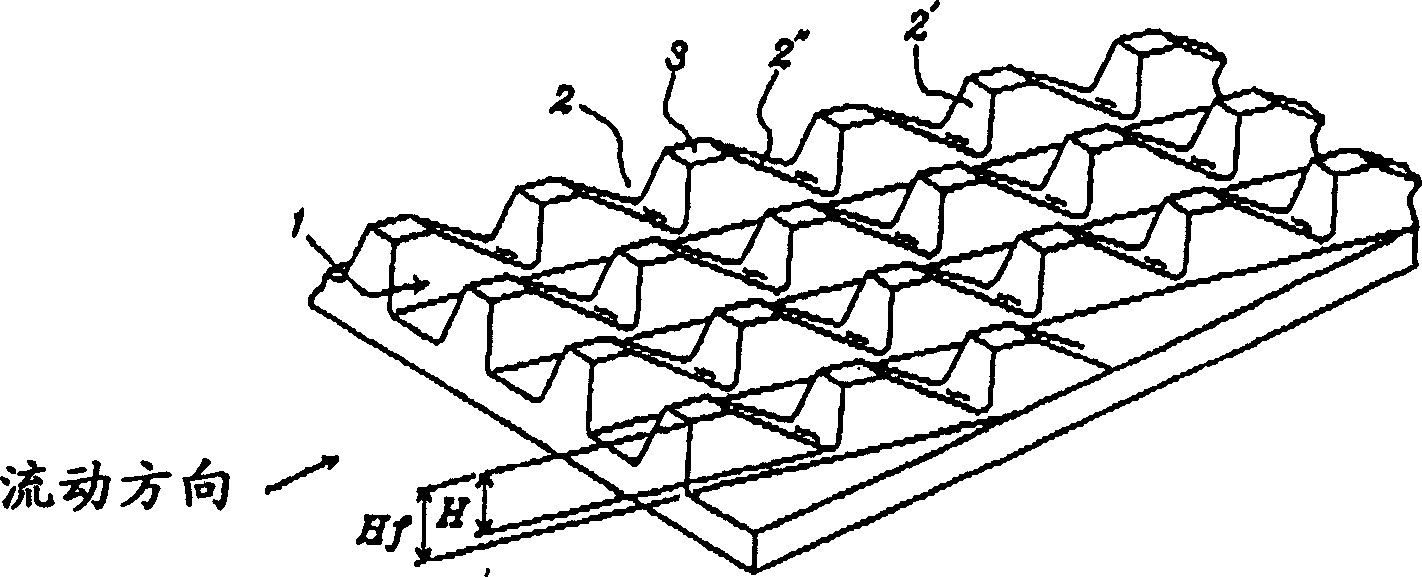
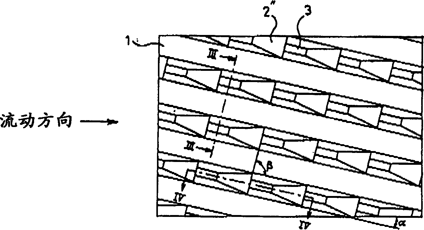
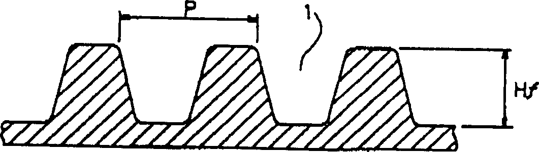
[0028] The heat transfer tube with cross grooves of the present invention is a metal tube with a circular cross section. A plurality of spiral grooves 1 are formed on the entire inner surface of the tube. These spiral grooves 1 are parallel to each other and form a certain spiral angle with respect to the longitudinal axis of the tube. α. Such as image 3 As shown, the cross-sectional shape of the spiral groove 1 is an inverted trapezoid. In addition, the heat transfer tube with intersecting grooves is also provided with a plurality of sub-grooves 2 which are parallel to each other and cross the spiral groove 1 at a certain angle β. Such as Figure 4 As shown, the cross-sectional shape of the auxiliary groove is basically a right triangle, with a helix angle larger than that of the helical groove. The spiral groove 1 and the sub groove 2 form a plurality of trapezoidal fine protrusions 3 on the inner surface of the tube.
[0029] The heat transfer tube is made of common materials such as copper and copper alloy, aluminum and aluminum alloy. The width and thickness of the metal sheet used to make the tube can be appropriately selected according to the application.
[0030] Such as Figure 5 As shown, the secondary groove 2 is formed first, and then the spiral groove 1 is formed. The cross-sectional shape of the spiral groove 1 is the same as that of a general heat transfer tube with cross grooves. It is triangular or trapezoidal. The spiral groove 1 is relative to the longitudinal axis of the tube. The helical angle α, that is, the angle relative to the flow direction of the refrigerant fluid is 10°-40°, preferably 18°-25°. If the inclination angle α of the spiral groove is less than 10°, the turbulence effect of the spiral groove is not easily obtained, the turbulence effect on the refrigerant fluid is reduced, and the heat transfer performance is poor. Conversely, if the spiral angle α is greater than 40°, the resistance of the spiral groove to the fluid increases sharply, and the pressure loss increases.
[0031] The pitch P between the spiral grooves is preferably 0.2 to 0.7 mm. If the pitch P of the grooves is too large, the formation density of the spiral grooves is low, and the effect of improving the fluidity and heat transfer performance of the refrigerant fluid is reduced. Conversely, if the pitch of the grooves is too small, the formation of the grooves is difficult. Therefore, for general heat transfer tubes with an inner diameter of about 1 cm, the pitch is preferably in the range of 0.2 to 0.7 mm.
[0032] The ratio Hf/Di of the depth Hf of the spiral groove 1 to the inner diameter Di of the pipe is preferably in the range of 0.02 to 0.05. When the ratio of the depth of the spiral groove to the inner diameter of the pipe is 0.02 or less, there is no effect of the spiral groove, and the surface tension and turbulence effects generated by the spiral groove cannot be obtained. Conversely, when Hf/Di is 0.05 or more, the resistance of the spiral groove to the fluid increases, and the fluidity decreases.
[0033] In the present invention, the refrigerant fluid caused by the continuous spiral groove can be prevented from spreading widely. At the same time, in order to further improve the turbulent flow of the refrigerant fluid and the stirring effect of the spiral groove, a plurality of spiral grooves 1 and parallel to each other are formed.的副槽2. Such as figure 2 As shown, the crossing angle β of the spiral groove 1 and the auxiliary groove 2 is preferably in the range of 75° to 105°, preferably at right angles to each other.
[0034] The inclination angle γ of the back 2" of the downstream side of the auxiliary tank 2 with respect to the tube axis direction, that is, with respect to the flow direction of the refrigerant 2 The inclination angle γ 2′ ahead of the upstream side of the spiral groove 1 1 small. Such as Figure 4 As shown, the inclination angle γ of the front 2′ on the upstream side 1It is approximately at right angles to the flow direction of the refrigerant fluid, preferably within the range of 90°~105°, the inclination angle γ of the back side of the downstream side is 2″ 2 It is preferably in the range of 30° to 60°.
[0035] Due to the above-mentioned structure, for the refrigerant fluid, the upstream front face 2'with a large inclination angle generates significantly greater turbulence and agitation than the prior art. Since the inclination angle of the downstream back 2" is gentle, as described later, when the refrigerant fluid flows over the protrusion 3, it slowly moves along the downstream back 2", so that the downstream back 2" does not The vortex is generated. Therefore, according to the present invention, the existing problem of the existing heat transfer tube with cross grooves, that is, the pressure loss can be minimized.
[0036] Such as Figure 4 As shown, the ratio A/B of the upper surface width A of the protrusion 3 to the upper opening width B of the sub groove 2 is preferably in the range of 0.2 to 1.0. If A/B is less than 0.2, that is, the upper surface width A of the protrusion 3 is too small, when the spiral groove is processed after the formation of the secondary groove 2, the front surface 2'of the protrusion 3 is inclined upward. Therefore, it is not easy to process the inclination angle of the secondary groove to the required angle. Conversely, if A/B is greater than 1.0, that is, the upper surface width A of the protrusion is too large, the liquid film spreads on the upper surface of the protrusion, and the condensation performance is reduced.
[0037] The depth Hf of the spiral groove is preferably the same as the depth of the sub groove. If the sub groove is deeper than the spiral groove, it will adversely affect the turbulence effect of the spiral groove and the fluidity caused by the surface tension inside the groove. Therefore, the depth of the secondary groove should not be greater than the depth of the spiral groove H/Hf≤1.0. If the depth of the secondary groove is excessively smaller than the depth of the spiral groove, there is no big difference in heat transfer performance compared with a general spiral grooved tube. Therefore, it should be at least 1/2 of the depth of the spiral groove H/Hf≥0.5.
[0038] Below, refer to Figure 5 The manufacturing method of the heat transfer tube with cross grooves of the present invention is described. The manufacturing method of the heat transfer tube with cross grooves of the present invention is not particularly different from the general manufacturing method of the electric welding heat transfer tube. (See Japanese Patent Publication No. 94-234014). However, the characteristic of the method of the present invention is that the secondary groove is formed first, and then the spiral groove is formed. The general manufacturing method of heat transfer tubes with cross grooves is to first form the spiral grooves, and then form the auxiliary grooves. In this way, when the auxiliary grooves are processed, the protrusions are formed inside the spiral grooves, which has an impact on the fluidity of the refrigerant fluid. Adverse effects. The method of the present invention can effectively prevent this adverse effect.
[0039] The manufacturing method of the present invention is to first pass the metal sheet 5 with the required width through the roller 6 to form the auxiliary groove 2 at a certain interval, and then pass the roller 7 to form the spiral groove 1 at a certain interval. At each roller 6, 7, a protrusion corresponding to the shape of each groove is formed at a predetermined angle. As mentioned above, the sub-groove is approximately a right-angled triangle. Therefore, when the spiral groove is formed, the flow of metal from the press-in portion is almost used to form the trapezoidal protrusion 3. Even if a certain degree of protrusion is protruded on the sub groove, the fluidity improvement effect of the spiral groove will not be reduced. In addition, the sharp protrusions protruding on the auxiliary grooves effectively prevent the diffusion of the cooling fluid and improve the condensation performance.
[0040] After forming the sub-groove and the spiral groove in the metal sheet, the sheet is passed through one or more stages of forming rolls 8 with the groove formed facing the inner surface, and the sheet is formed into a tube with a predetermined diameter. Then, the induction coil 9 is used for high-frequency welding, and the two sides of the metal plate are welded to form a tube. Finally, as required, the welded pipe is passed through the shaping roller 10 to form the outer peripheral surface of the pipe into a perfect circle. The fabricated tube with cross grooves is rolled into a spiral shape or cut into a predetermined length, and the fabrication of the tube is finally completed.
[0041] The heat transfer tube with intersecting grooves of the present invention constructed as described above has sub grooves formed at a predetermined angle with the spiral grooves, so it can overcome the shortcomings of the continuous spiral grooves in the prior art, that is, the fluid flows along the spiral. The groove spreads widely to most of the inner surface of the heat transfer tube, and the metal surface does not directly contact the refrigerant fluid, which reduces the condensation efficiency. In addition, as described above, the shape of the sub groove is such that any one side wall is almost at a right angle with respect to the longitudinal axis, and the other side wall is inclined at a certain angle. Therefore, the refrigerant fluid flows smoothly along the inclined wall, suppresses the generation of eddy currents at the back of the downstream side of the protrusion, and prevents the increase in flow resistance and the deterioration of heat transfer performance caused by the eddy currents. Since the vertical wall has the greatest effect on the turbulence and stirring of the fluid, it can improve the heat transfer performance. In addition, since the width of the lower portion of the protrusion between the sub groove and the sub groove is large, even when the heat transfer tube is used, the groove or the protrusion is less likely to be damaged even if the tube is expanded.
[0042] Since the secondary groove is processed first and the spiral groove is processed later, it is possible to prevent the formation of protrusions on the inside of the spiral groove, thereby effectively preventing adverse effects on the fluidity of the refrigerant fluid. In addition, the sharp protrusions protruding on the sub-tank can effectively prevent the diffusion of the fluid and improve the evaporation performance.
[0043] In order to confirm the effect of the heat transfer tube with cross grooves of the present invention, an experiment was done, Figure 6 to Figure 8 That is to say, the graph showing the results of the experiment shows that the evaporation/condensation performance and pressure loss value of the heat transfer tube with cross grooves of the present invention made of copper with an inner diameter of 9.52 mm are the same as those of the conventional grooveless heat transfer tube ( Comparison curves of smooth tube), heat transfer tube with spiral groove and heat transfer tube with cross groove. The spiral angle α of the spiral groove of the heat transfer tube with cross grooves of the present invention used in the experiment is 18°, the intersection angle β of the auxiliary groove with respect to the spiral groove is 90°, and the pitch P of the spiral groove is 0.24 mm. The ratio of the depth of the groove to the inner diameter of the pipe Hf/Di is 0.025, the ratio of the depth of the auxiliary groove to the depth of the spiral groove is 0.8, and the vertical wall inclination angle γ of the auxiliary groove 1 Is 90°, the inclination angle of the inclined wall γ 2 At 30°, the ratio A/B of the upper surface width A of the protrusion 3 to the upper opening width B of the sub-groove is 0.5. The above-mentioned heat transfer tube was used to make a double-tube type heat exchanger, the refrigerant R22 was flowed into the tube, and various performances were measured.
[0044] From Figure 6 with Figure 7 The results of the heat transfer performance experiment show that when the heat transfer tube with cross grooves of the present invention is used, the heat transfer performance is almost the same as that of the existing heat transfer tube with cross grooves, which is about 3 times that of a smooth tube and a spiral groove tube. About 1.5 times or more, especially the condensing performance is significantly improved than the existing heat transfer tube with cross grooves.
[0045] From Figure 8 The experimental results of the internal pressure loss of the tube show that although the heat transfer performance is improved, the internal pressure loss of the tube is similar to the existing heat transfer tube with spiral grooves, and is significantly reduced compared to the existing heat transfer tube with cross grooves.
[0046] It can be seen from the above that the heat transfer tube with cross grooves and the manufacturing method thereof of the present invention can greatly improve heat transfer performance such as evaporation performance and condensation performance without increasing the pressure loss inside the tube. Therefore, the performance of the heat exchanger such as the condenser, the evaporator, and the heating tube can be improved, which not only saves energy, but also enables the heat exchanger to be miniaturized, lightened, and reduced in manufacturing cost.

PUM

no PUM

Description & Claims & Application Information

We can also present the details of the Description, Claims and Application information to help users get a comprehensive understanding of the technical details of the patent, such as background art, summary of invention, brief description of drawings, description of embodiments, and other original content. On the other hand, users can also determine the specific scope of protection of the technology through the list of claims; as well as understand the changes in the life cycle of the technology with the presentation of the patent timeline. Login to view more.
Why Eureka
Try Eureka