Device and method for testing the contents of a switchgear cabinet following installation according to a plan

A switchgear and equipment technology, applied in switchgear, substation/switch layout details, program control, etc., can solve problems such as complexity and error-proneness, and achieve the effect of reducing failure factors and eliminating manual inspection.

Pending Publication Date: 2021-03-19
RITTALWERK RUDOLF LOH GMBH & CO KG
View PDF9 Cites 0 Cited by
  • Summary
  • Abstract
  • Description
  • Claims
  • Application Information

AI Technical Summary

Problems solved by technology

This manual inspection of the switchgear contents after assembly requires the preparation of a verifiable inspection protocol and is error-prone based on the complexity of the interconnected technical components

Method used


Image

  • Device and method for testing the contents of a switchgear cabinet following installation according to a plan
  • Device and method for testing the contents of a switchgear cabinet following installation according to a plan

Examples


Embodiment Construction

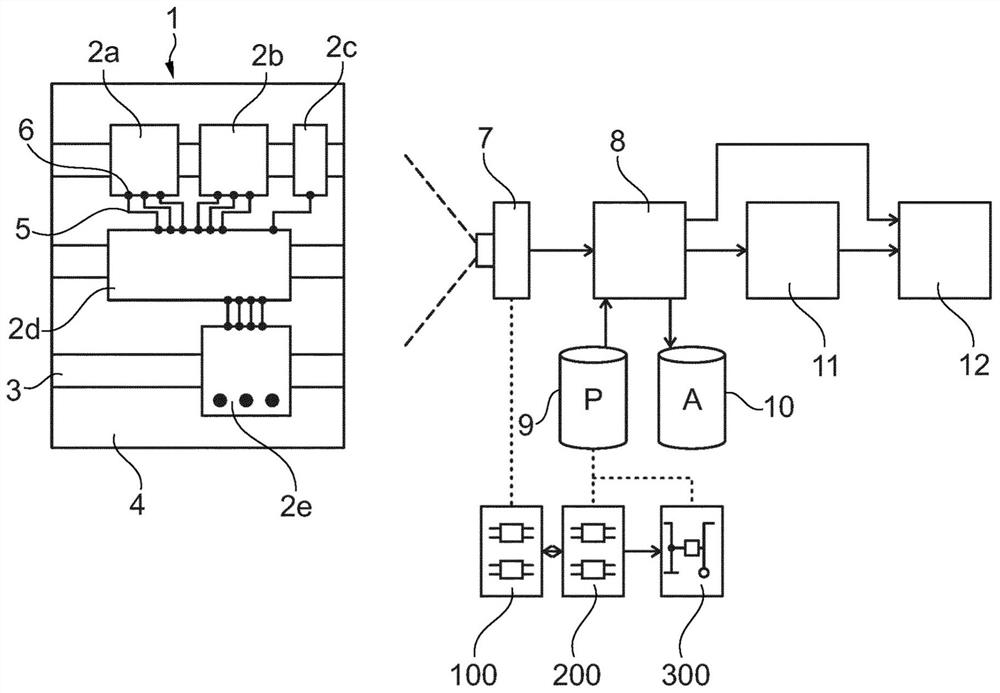
[0027] according to figure 1, after assembly during the manufacturing process, the switchgear 1 is to be tested, the contents of the switchgear comprising various technical components 2a to 2e, which are mounted via top hat rails 3 on the mounting plate 4 of the switchgear 1 and Wiring to each other is via various electrical lines 5 (exemplary). For this purpose, the components 2a to 2e each have a corresponding terminal connection 6 (example) which is designed as a screw or plug-in terminal arrangement.

[0028] In order to inspect the contents of the switchgear 1, the switchgear 1 is assigned a camera unit 7 arranged at a distance from the switchgear 1 and aligned with the mounting plate 4, which generates an image of the fully mounted and wired components 2a to 2e on the mounting plate 4 3D image. An evaluation unit 8 connected downstream of the camera unit 7 performs an image-processed comparison between the image layout 100 of the actual state of the housing contents re...


PUM


Abstract

The invention relates to a device for testing the contents of a switchgear cabinet following installation of equipment components (2a-2e) according to a plan and the wiring thereof via terminals (6) provided therefor by means of designated electrical cables (5), comprising: - a camera unit (7) for the at least two-dimensional image capture of the components (2a-2e) fully installed and wired on aninstallation board (4) of a switchgear cabinet (1); - an evaluation unit (8) for carrying out a comparison between an imaged layout (100), on the basis of the image capture, of the actual state with aprovided plan layout (200) of the target state, at least with regard to: a) the completeness and position of the installed components (2a-2e), b) the allocation of electrical terminals (6), c) the routing of the electrical cables (5); - an output unit (11) for providing the test result on the structural consistency of the switchgear cabinet (1) for an assessment with regard to delivery approval or fault rectification.

Description

technical field [0001] The invention relates to a device and a method for testing the contents of a switch cabinet after the technical components have been assembled according to plan and they have been wired via terminal contacts provided for this purpose by means of marked electrical lines. Furthermore, the invention also relates to a computer program product implementing the method. Background technique [0002] The field of the invention relates to switchgear. Switchgear is mainly used in the case of industrial applications. Switchgear cabinets of the type concerned here accommodate technical components, which are usually designed in the form of standardized electrical or electronic built-in modules. These technical components are mainly used to control automated production systems, process engineering systems, machine tools, etc. The built-in modules that are grouped together in the switch cabinet are usually technical components that are not arranged directly on the...

Claims


Application Information

Patent Timeline
IPC IPC(8): H02B3/00H02B1/20H02B1/32
CPCG05B2219/37205H02B1/202H02B1/32H02B3/00G06T7/001G06T2207/10028
Inventor 托马斯·魏克塞尔托马斯·米歇尔斯拉尔斯·马丁尤迪特·扎赫莱
Owner RITTALWERK RUDOLF LOH GMBH & CO KG
Why Eureka
Try Eureka