
Surgical tool cleaning device for gastrointestinal surgery in hospital

A technology for surgical tools and cleaning equipment, which is applied in the field of surgical tool cleaning equipment for gastrointestinal surgery in hospitals, can solve the problems of complicated operation and unclean cleaning, and achieve the effect of easy and sufficient cleaning

Active Publication Date: 2021-03-23
PINGDU PEOPLES HOSPITAL
View PDF3 Cites 0 Cited by
  • Summary
  • Abstract
  • Description
  • Claims
  • Application Information

AI Technical Summary

Problems solved by technology

[0005] In order to overcome the shortcomings of complicated operation and unclean cleaning, the object of the present invention is to provide a surgical tool cleaning equipment for hospital gastrointestinal surgery that improves the cleanliness of surgical tools, realizes full cleaning, and automates and simplifies the operation process.

Method used


Image

  • Surgical tool cleaning device for gastrointestinal surgery in hospital
  • Surgical tool cleaning device for gastrointestinal surgery in hospital
  • Surgical tool cleaning device for gastrointestinal surgery in hospital

Examples


Embodiment 1

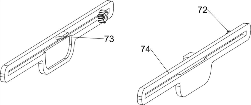
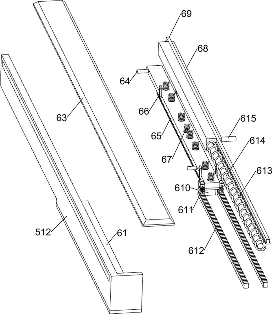
[0075] A hospital gastrointestinal surgery surgical tool cleaning equipment, such as figure 1 As shown, it includes a bottom plate 1, a leg 2, a placement mechanism 3 and a spray mechanism 4. Two legs 2 are connected to the front and rear sides of the upper part of the bottom plate 1. The upper side of the bottom plate 1 is connected to the placement mechanism 3. The upper side of the bottom plate 1 is connected to a Spray mechanism4.

[0076] When the device needs to be used, the user can open the placement mechanism 3, place the surgical tool in the placement mechanism 3, and close the placement mechanism 3 to achieve the purpose of placing the surgical tool and facilitating subsequent operations. The user can pull the sprayer backwards Mechanism 4, pour clean water into the spray mechanism 4, push the placement mechanism 3 forward, and then push the spray mechanism 4 forward, the clean water is sprayed from the spray mechanism 4, and the surgical tools in the placement mech...

Embodiment 2

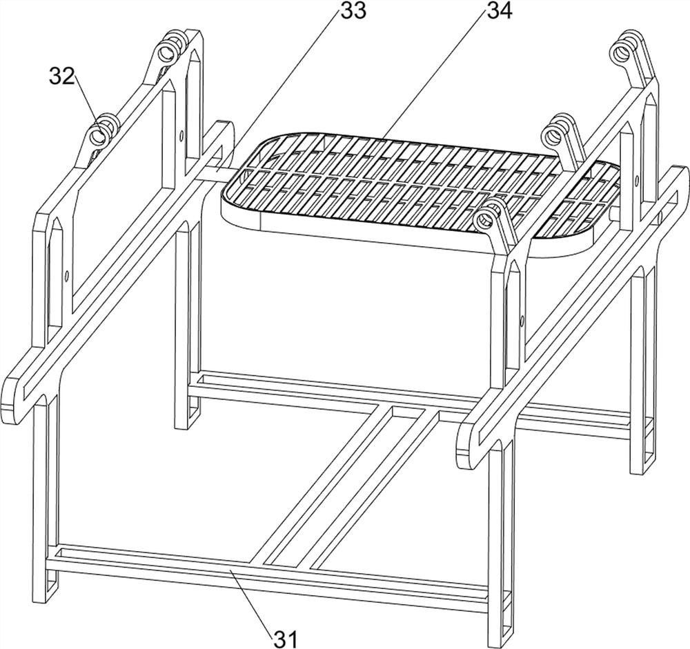
[0078] On the basis of Example 1, such as figure 2 As shown, the placement mechanism 3 includes a placement rack 31, a spray rack 32, a first guide rod 33, and a placement tray 34. The upper side of the bottom plate 1 is connected with the placement rack 31, and the left and right sides of the upper part of the placement rack 31 are connected with a plurality of spray nozzles. Both sides of the shower rack 32 and the placement rack 31 slide and are rotatably connected with a first guide rod 33 , and a placement tray 34 is connected between the inner sides of the first guide rod 33 .

[0079] When the device needs to be used, the user can open the placement tray 34, place the surgical tools in the placement tray 34, and close the placement tray 34 to achieve the purpose of placing the surgical tools and facilitating subsequent operations, continue the follow-up operations, and push forward The tray 34 is placed, and the forward movement of the tray 34 drives the first guide ro...


PUM


Abstract

The invention relates to a cleaning device, and particularly relates to a surgical tool cleaning device for gastrointestinal surgery in a hospital. The invention aims to provide the surgical tool cleaning device for gastrointestinal surgery in the hospital, which can improve the cleanliness of surgical tools, realize full cleaning and realize an automatic and simplified operation process. The technical scheme of the invention is as follows: the surgical tool cleaning device for gastrointestinal surgery in the hospital comprises supporting legs, a placing mechanism and a spraying mechanism, wherein two supporting legs are connected to each of two sides of the top of a bottom plate; the placing mechanism is connected to the top side of the bottom plate; and the spraying mechanism is connected to the top side of the bottom plate. According to the surgical tool cleaning device for gastrointestinal surgery in the hospital, through the cooperation of a placing frame, a spraying frame, a first guide rod and a placing disc, the purposes of placing the surgical tools and facilitating subsequent operation are achieved.

Description

technical field [0001] The invention relates to a cleaning device, in particular to a cleaning device for surgical tools used in gastrointestinal surgery in a hospital. Background technique [0002] Medical instruments such as scalpels, surgical scissors, bone forceps, burs, and dental extraction forceps are all reusable, so cleaning and disinfection after use are extremely important, because it is related to the safety of the next doctor and patient. Cleaning If the disinfection is not thorough, it will infect other personnel and cause a lot of unnecessary troubles. [0003] When nurses work in the hospital supply room, they manually clean the instruments placed in the basket. The faucet is inconvenient to use. The faucet in the department cannot be turned, so the instruments can only be placed underneath for washing, and the bottom cannot be rinsed. The common water pipe commonly used by nurses is connected to the faucet. Flushing, but the water pipe is too thick, it is e...

Claims


Application Information

Patent Timeline
IPC IPC(8): A61B90/70A61B50/33
CPCA61B90/70A61B50/33Y02B40/00
Inventor 刘永群
Owner PINGDU PEOPLES HOSPITAL
Learn More