Positive pole plate for improving rate capability of lithium ion battery as well as preparation method and application of positive pole plate
A lithium-ion battery and positive electrode technology, which is applied in the direction of battery electrodes, non-aqueous electrolyte battery electrodes, and positive electrodes, can solve problems such as unfavorable battery energy density and improvement, and achieve improved battery rate discharge performance, simple operation, and improved battery performance. The effect of energy density
- Summary
- Abstract
- Description
- Claims
- Application Information
AI Technical Summary
Problems solved by technology
Method used
Image
Examples
preparation example Construction
[0048] The preparation method of the present invention will be further described in detail in conjunction with specific examples below. It should be understood that the following examples are only for illustrating and explaining the present invention, and should not be construed as limiting the protection scope of the present invention. All technologies realized based on the above contents of the present invention are covered within the scope of protection intended by the present invention.
[0049]Unless otherwise specified, the experimental methods used in the following examples are conventional methods; the reagents and materials used in the following examples, unless otherwise specified, can be obtained from commercial sources.
[0050] The aluminum mesh used in the following examples is selected from aluminum meshes with a mesh number of 500 and a thickness of 10 μm.
Embodiment 1
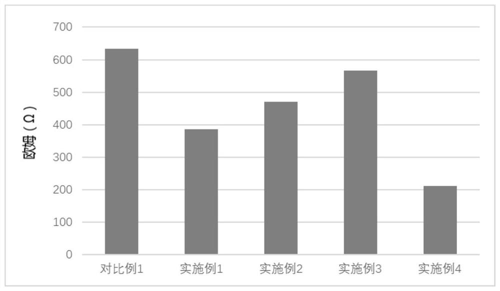
[0058] Others are the same as Comparative Example 1, the difference is that a layer of aluminum mesh is inserted in the positive electrode layer, and the total thickness of the positive electrode layer remains unchanged; that is, when coating, a layer of positive electrode layer with a thickness of 75 μm is first coated on both sides of the current collector and named positive electrode Layer X, add a layer of aluminum mesh on the surface of the positive electrode layer X, and vacuum bake at 95°C for 2-4h; then coat a layer of positive electrode layer with a thickness of 75μm on the aluminum mesh and name it as positive electrode layer Y. Welded together with aluminum strips, baked in vacuum at 95°C for 8 hours, and obtained the positive electrode sheet, the results are as follows figure 1 As shown, a positive electrode layer X5, an aluminum mesh 3 and a positive electrode layer Y5 are respectively arranged on both sides of the current collector 1;
Embodiment 2
[0060] Others are the same as Comparative Example 1, the difference is that a layer of aluminum mesh is inserted in the positive electrode layer, and the total thickness of the positive electrode layer becomes thicker; that is, when coating, a layer of positive electrode layer with a thickness of 80 μm is first coated on both sides of the current collector and named as the positive electrode Layer X, add a layer of aluminum mesh on the surface of the positive electrode layer X, and vacuum bake at 95°C for 2-4h; then coat a layer of positive electrode layer with a thickness of 80μm on the aluminum mesh and name it as the positive electrode layer Y, and combine the aluminum mesh with the current collector They were welded together with aluminum strips, and baked in vacuum at 95°C for 8 hours to obtain the obtained positive electrode sheet.
PUM
| Property | Measurement | Unit |
|---|---|---|
| Thickness | aaaaa | aaaaa |
| Thickness | aaaaa | aaaaa |
| Mesh | aaaaa | aaaaa |
Abstract
Description
Claims
Application Information
 - R&D Engineer
- R&D Manager
- IP Professional
- Industry Leading Data Capabilities
- Powerful AI technology
- Patent DNA Extraction
Browse by: Latest US Patents, China's latest patents, Technical Efficacy Thesaurus, Application Domain, Technology Topic, Popular Technical Reports.
© 2024 PatSnap. All rights reserved.Legal|Privacy policy|Modern Slavery Act Transparency Statement|Sitemap|About US| Contact US: help@patsnap.com


