Check patentability & draft patents in minutes with Patsnap Eureka AI!

Method for operating a synchronous motor excited by permanent magnets, electronic control device, motor arrangement, and storage medium

A technology of synchronous motors and permanent magnets, which is applied in the direction of controlling electromechanical transmission devices, electrical devices, control devices, etc.

Pending Publication Date: 2021-03-23
CONTINENTAL AUTOMOTIVE TECH GMBH
View PDF6 Cites 0 Cited by
  • Summary
  • Abstract
  • Description
  • Claims
  • Application Information

AI Technical Summary

Problems solved by technology

This may require limiting the total consumed power in current loads such as permanent magnet excited synchronous motors

Method used


Image

  • Method for operating a synchronous motor excited by permanent magnets, electronic control device, motor arrangement, and storage medium
  • Method for operating a synchronous motor excited by permanent magnets, electronic control device, motor arrangement, and storage medium
  • Method for operating a synchronous motor excited by permanent magnets, electronic control device, motor arrangement, and storage medium

Examples


Embodiment Construction

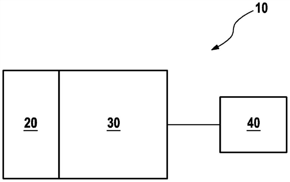
[0029] figure 1 A motor arrangement 10 according to an exemplary embodiment of the invention is shown. The electric machine arrangement 10 includes a control device 20 , a converter 30 and a permanently-magnet-excited synchronous machine 40 . The control device 20 is designed to control the converter 30 , which in turn controls the electric machine 40 and thus not only supplies the electric machine with power but also predefines its desired operation, in particular a desired torque.

[0030] The control device 20 is especially configured for carrying out the method according to the invention. This is based on the following considerations.

[0031] The power consumption of a permanent magnet excited synchronous motor can basically be calculated as follows:

[0032]

[0033] in:

[0034] u DC is an applied voltage, which may in particular be a predetermined vehicle electrical system voltage,

[0035] I DC for the predetermined maximum current,

[0036] u d is the d c...


PUM


Abstract

The invention relates to a method for operating a synchronous motor excited by permanent magnets, wherein a desired voltage vector having a desired value is calculated in such a way that the power limitation is maintained for the best possible adherence to a torque requirement. The invention further relates to an associated control device, an associated motor arrangement and an associated storagemedium.

Description

technical field [0001] The invention relates to a method for operating a permanent-magnet-excited synchronous machine as well as a control device, a machine arrangement and a storage medium for carrying out the method. Background technique [0002] For example, permanently excited synchronous motors can be used in motor vehicles to generate pressure in the braking system. Such electric machines are usually supplied via the on-board electrical system of the motor vehicle, in which there are a plurality of components which are corresponding power sources or power consumers (Leistungssenke). In order to stably operate such an on-vehicle power grid, it is generally necessary to achieve a balance between power generation and current consumption. This may require limiting the overall consumed power in a current load such as a permanently excited synchronous machine. This power can be calculated, for example, by multiplying the operating voltage of the vehicle electrical system b...

Claims


Application Information

Patent Timeline
IPC IPC(8): H02P21/00H02P29/40H02P25/022H02P29/032B60L7/00
CPCH02P21/00H02P25/022H02P29/032B60L3/12B60L50/14B60L2220/14B60L2240/427B60L2240/429Y02T10/7072H02P29/40Y02T10/64H02P21/22B60R16/03H02P27/12H02P2207/05
Inventor D·舒尔特B·布迪阿努E·巴特尔T·考夫曼
Owner CONTINENTAL AUTOMOTIVE TECH GMBH
Features
  • R&D
  • Intellectual Property
  • Life Sciences
  • Materials
  • Tech Scout
  • Unparalleled Data Quality
  • Higher Quality Content
  • 60% Fewer Hallucinations
Learn More