
Pan-tilt control method and pan-tilt

A control method and PTZ technology, applied in the PTZ field, can solve the problems of inconvenient control of the screen direction of the operator, inability to give full play to the different characteristics of the control device, and poorly defined function design.

Inactive Publication Date: 2021-03-23
SZ DJI TECH CO LTD
View PDF5 Cites 2 Cited by
  • Summary
  • Abstract
  • Description
  • Claims
  • Application Information

AI Technical Summary

Problems solved by technology

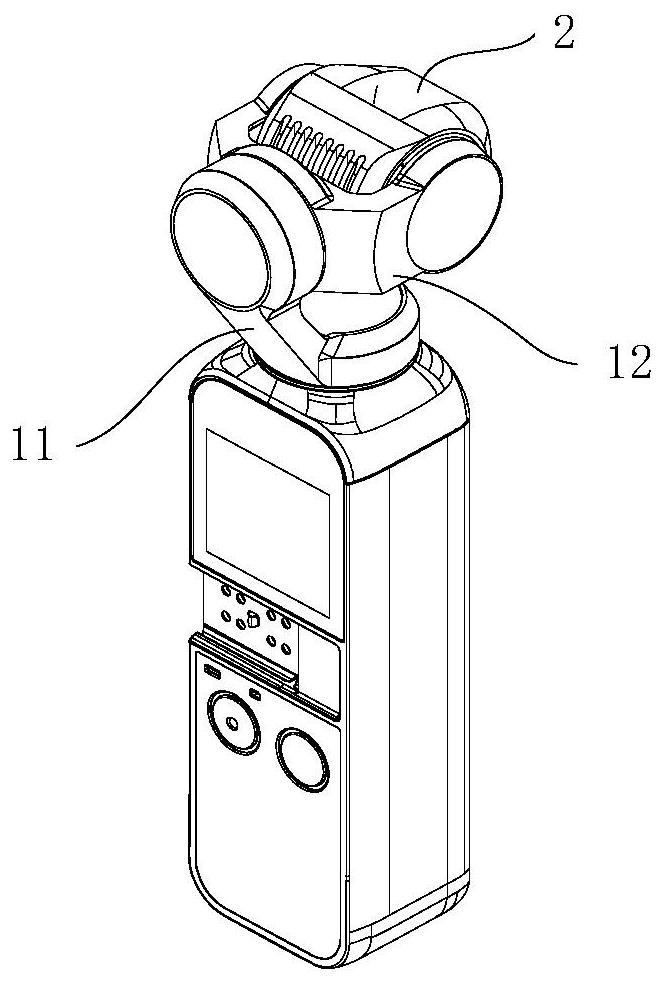
[0002] In the first-person perspective FPV (First Person View) following mode, due to poorly defined function design or technical limitations, the existing gimbal either does not realize joystick control, or realizes joystick control on the joint coordinate system. To meet the needs of different application scenarios, it is impossible to fully utilize the different characteristics of various control devices, and it is not convenient for the operator to control the direction of the screen

Method used


Image

  • Pan-tilt control method and pan-tilt
  • Pan-tilt control method and pan-tilt
  • Pan-tilt control method and pan-tilt

Examples


Embodiment Construction

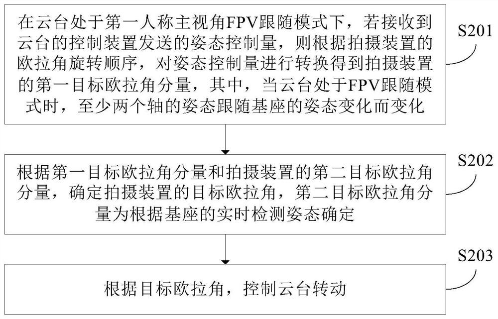
[0028] In the FPV (First Person View) following mode of the existing gimbal, joystick control can be realized on the joint coordinate system. For example, when the control device is a remote control, the amount of stick generated by the remote sensor may correspond to a joint Angle rotation, the gimbal controls one joint angle correspondingly, and other joint angles are not affected. The picture captured by the shooting device rotates around the joint coordinate system, and the picture may not meet the user's expectations. Therefore, this method of realizing joystick control on the joint coordinate system The method is not convenient for the operator to realize the control of the screen direction. Among them, in the joint coordinate system, each axis of the gimbal moves independently.

[0029] For this, the application converts the attitude control amount sent by the control device to obtain the first target Euler angle component of the shooting device according to the Euler a...


PUM


Abstract

Provided are a pan-tilt control method and a pan-tilt, the pan-tilt is mounted on a base, a shooting device is mounted on the pan-tilt, the pan-tilt is configured to rotate around at least two axes, and the method comprises the steps that when the pan-tilt is in a first-person main viewing angle FPV following mode, if a posture control quantity sent by a control device of the pan-tilt is received,the pan-tilt rotates around at least two axes; if yes, converting the attitude control quantity according to the Euler angle rotation sequence of the shooting device to obtain a first target Euler angle component of the shooting device; determining a target Euler angle of the shooting device according to the first target Euler angle component and a second target Euler angle component of the shooting device, the second target Euler angle component being determined according to a real-time detection attitude of the base; controlling the holder to rotate according to the target Euler angle; whenthe pan-tilt is in the FPV following mode, the postures of the at least two shafts change along with the posture change of the base. When the holder is controlled to rotate, the picture of the shooting device rotates around the world coordinate system, and the picture better conforms to the expectation of a user.

Description

technical field [0001] The present application relates to the field of cloud platforms, in particular to a method for controlling the platform and the platform. Background technique [0002] In the following mode of FPV (First Person View) in the first person perspective, the existing gimbals either do not realize joystick control due to poorly defined function design or technical limitations, or realize joystick control on the joint coordinate system. To meet the needs of different application scenarios, it is impossible to give full play to the different characteristics of various control devices, and it is not convenient for the operator to realize the control of the direction of the screen. Contents of the invention [0003] The present application provides a method for controlling a pan-tilt and the pan-tilt. [0004] According to the first aspect of the present application, there is provided a control method of a pan-tilt, the pan-tilt is mounted on a base, a photog...

Claims


Application Information

Patent Timeline
Patent Type & Authority Applications(China)
IPC IPC(8): H04N5/232G05D3/12
CPCG05D3/12H04N23/66H04N23/62H04N23/695
Inventor 林荣华
Owner SZ DJI TECH CO LTD
Learn More