Screening device for waste rock processing

A screening device and sieve plate technology, applied in the direction of filter screen, solid separation, grille, etc., can solve the problems of inability to crush stone, reduce work efficiency, blockage of waste stone of filter plate, etc.

Inactive Publication Date: 2021-03-26
邵阳县和谐环保科技有限公司
View PDF10 Cites 3 Cited by
  • Summary
  • Abstract
  • Description
  • Claims
  • Application Information

AI Technical Summary

Problems solved by technology

[0004] But above-mentioned patent still has some general problems in use process, and filter plate is easily blocked by waste rock in the process of filtering, although broom is arranged to clean it, can not continue to crush stone in the process of cleaning, reduces work efficiency

Method used


Image

  • Screening device for waste rock processing
  • Screening device for waste rock processing
  • Screening device for waste rock processing

Examples


Embodiment 1

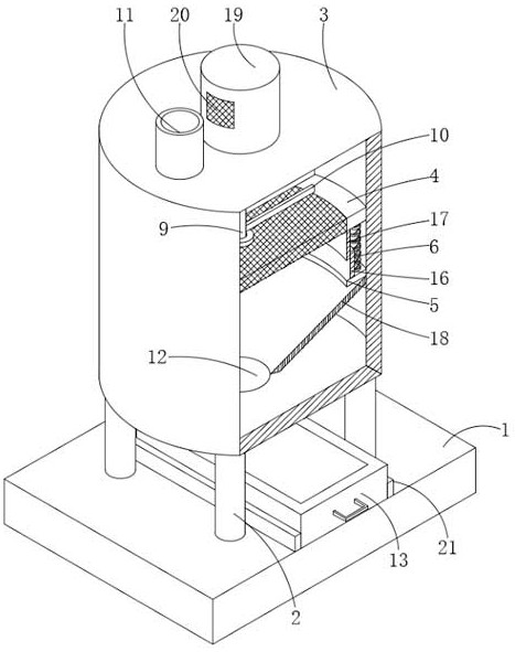
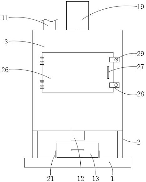
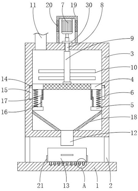
[0028] see Figure 1-6 , the present invention provides a technical solution: a screening device for waste rock processing, comprising a base 1, the four corners of the top of the base 1 are fixedly installed with a pillar 2, the top of the pillar 2 is fixedly installed with a crushing box 3, and the inside of the crushing box 3 The cavity is provided with a sieve plate 4, the inner wall of the crushing box 3 and the bottom of the sieve plate 4 are fixedly installed with a fixed plate 5, and the top of the fixed plate 5 is equidistantly fixed with a spring 6, and the top of the spring 6 is fixed to the bottom of the sieve plate 4 Installation, the top of the crushing box 3 is provided with a motor 7, the output shaft of the motor 7 is fixedly installed with a rotating rod 8, and the bottom of the rotating rod 8 runs through the crushing box 3 and extends to the inner cavity of the crushing box 3. , both sides of the rotating rod 8 and located in the inner cavity of the rotatin...

Embodiment 2

[0031] see Figure 1-6The difference between the present embodiment 2 and the embodiment 1 is that: both sides of the sieve plate 4 are fixedly installed with a limit block 14, and the inner wall of the crushing box 3 is provided with a limit groove 15 that is compatible with the limit block 14. The surface of the position block 14 is slidingly connected with the inner wall of the limiting groove 15, the top of the fixed plate 5 and one side of the spring 6 are fixedly installed with a first sealing tube 16, and the inner wall of the first sealing tube 16 is slidingly connected with a second sealing tube 17. The top of the second sealing pipe 17 is fixedly installed with the bottom of the sieve plate 4, and the inner cavity of the crushing box 3 is fixedly installed with a deflector 18 at the bottom of the fixed plate 5, and the bottom of the deflector 18 is connected with the inside of the crushing box 3. The bottom of the cavity is fixedly installed, and the deflector 18 is ...


PUM


Abstract

The invention discloses a screening device for waste rock processing. The screening device comprises a base, supporting columns are fixedly installed at the four corners of the top of the base, a crushing box is fixedly installed at the tops of the supporting columns, and a screening plate is arranged in an inner cavity of the crushing box. According to the screening device, through arrangement ofa spring, when a user uses the device, waste stone needing to be crushed is put into the inner cavity of the crushing box through a feeding pipe, an output shaft of a motor drives a rotating rod to rotate, a rotating rod rotates to drive the rotating pipe to rotate, the rotating pipe rotates to drive a crushing rod to crush the waste stone, the crushed broken stones fall into an inner cavity of acollecting box downwards through a discharging pipe after being filtered through a sieve plate, the waste stones fall onto the surface of the sieve plate downwards under the influence of the gravityof the waste stones and drive the sieve plate to move downwards, the spring is compressed downwards through movement of the sieve plate, at the moment, reacting force generated by contraction of the spring drives the sieve plate to move upwards, therefore, the sieve plate is in a shaking state and is prevented from being blocked by the broken stones.

Description

technical field [0001] The invention relates to the technical field of waste rock processing equipment, in particular to a screening device for waste rock processing. Background technique [0002] With the development of society, civil construction is developing vigorously, and large waste rocks will be produced during the construction process. Although people have done a lot of work on the prevention and control of waste rocks, the problem of waste rock treatment is still far from being solved, and must be strengthened. For environmental management of waste rocks, preventive measures should be strengthened. At the same time, domestic and foreign advanced technologies should be vigorously used to treat the generated waste rocks, so as to finally realize the harmlessness, reduction and resource reuse of waste rocks. [0003] Chinese patent No. CN201820990955.X discloses a recovery device for construction waste rocks with a crushing function, including a motor, a first fixed b...

Claims


Application Information

Patent Timeline
Patent Type & Authority Applications(China)
IPC IPC(8): B02C13/18B02C13/284B02C23/16B07B1/34B07B1/42
CPCB02C13/18B02C13/284B02C23/16B02C2023/165B07B1/34B07B1/42
Inventor 石飞跃唐配成
Owner 邵阳县和谐环保科技有限公司
Why Eureka
Try Eureka