A self-cooling hob to prevent chips from remaining

A self-cooling, hob technology, applied to components with teeth, gear teeth manufacturing devices, gear teeth, etc., can solve the problems of high cost, various varieties, chip removal and heat dissipation performance can not reach the ideal state, to achieve The effect of reducing the temperature of the hob and prolonging the life of the hob

Active Publication Date: 2022-04-29
南京迈森智能装备有限公司
View PDF27 Cites 0 Cited by
  • Summary
  • Abstract
  • Description
  • Claims
  • Application Information

AI Technical Summary

Problems solved by technology

However, in the process of flushing, it is difficult to flush out the chips at the bottom of the cutting edge, and there will still be residues, and the cutting fluid often has problems such as bacterial growth, complicated maintenance, various varieties, high cost, etc., and the chip removal and heat dissipation performance cannot be ideal. state

Method used


Image

  • A self-cooling hob to prevent chips from remaining
  • A self-cooling hob to prevent chips from remaining
  • A self-cooling hob to prevent chips from remaining

Examples


Embodiment 1

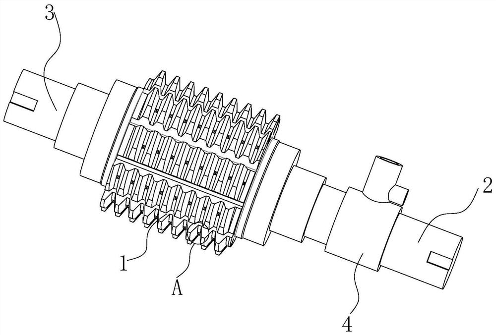
[0037] see Figure 1-7 Shown is a self-cooling hob that prevents chip residue, which is a self-cooling hob that can prevent gear tooth surface damage during processing. Specifically, a self-cooling hob that prevents chips from remaining includes a hob body 1 and a rotating installation head 4 .

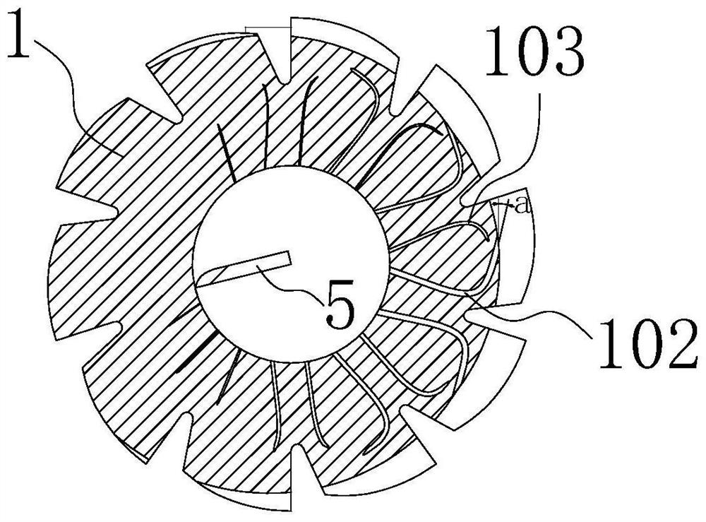
[0038] The two ends of the hob body 1 are respectively provided with a first mounting end 2 and a second mounting end 3 , a central hole 101 is opened in the hob body 1 , and a helical blade 5 is fixedly disposed in the central hole 101 .

[0039] A channel 201 is opened inside the first mounting end 2 , and the channel 201 communicates with the central hole 101 , and a through hole 202 is uniformly opened on the circumference side of the first mounting end 2 , and the through hole 202 communicates with the channel 201 .

[0040] The rotating connector 4 is rotatably installed on the first mounting end 2, and the rotating connecting head 4 covers the through hole 202. A dynamic seal ...

Embodiment 2

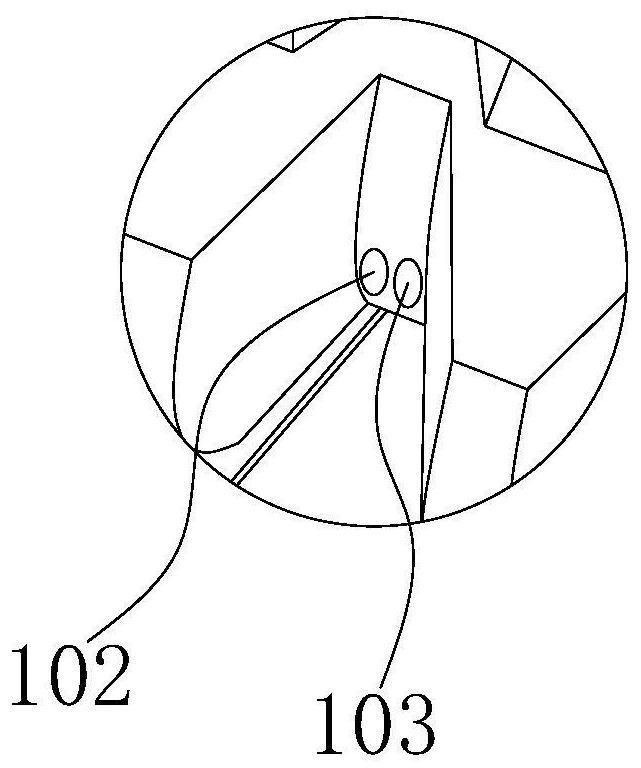
[0048] Another self-cooling hob that prevents chips from remaining is different from Embodiment 1 in that: the direction of the extension line of the liquid outlet of the first curved groove 102 and the second curved groove 103 and the tangential direction of the outlet end form an included angle a , the angle a is 20°.

Embodiment 3

[0050] The difference between another self-cooling hob that prevents chip residue from Embodiment 1 and Embodiment 2 is that: Figure 8 As shown, the pressure relief port 402 on the rotary joint 4 is removed, and a thin through hole 301 is opened on the second installation end 3 , and the thin through hole 301 communicates with the central hole 101 .


PUM


Abstract

The invention belongs to the technical field of metal cutting tools, and relates to a self-cooling hob that prevents chips from remaining. It is characterized in that it includes a hob body and a rotating installation head; At the installation end, a central hole is opened in the hob body, and a spiral blade is fixedly arranged in the center hole; a channel is opened inside the first installation end, and the channel communicates with the center hole; through holes are evenly opened on the circumferential side of the first installation end, and the through hole It communicates with the channel; the rotating connector is rotatably installed on the first installation end, and the rotating connector covers the through hole; the connecting port is provided on the rotating connecting head, and the connecting port communicates with the channel through the through hole; the rotating connecting head is also provided with a leak A pressure port and a pressure relief port are provided with a convex ring and a pressure relief valve, and the pressure relief port communicates with the channel through a through hole. The invention can not only flush away chips at the bottom of the cutting edge, but also reduce the influence of cutting heat on gear hobbing, reduce the temperature of the hob, and prolong the life of the hob.

Description

technical field [0001] The invention belongs to the technical field of cutting tools for metal cutting, and in particular relates to a self-cooling hob which prevents chips from remaining. Background technique [0002] When hobs are used to process workpieces such as gears and sprockets, defects such as high tooth surface roughness and strain often occur, resulting in waste or substandard products. The reason for this phenomenon is that chip removal is not smooth during machining, and a large amount of chips are deposited in the bottom of the cutting edge, forming built-up edge. A common solution is to use a large amount of cutting fluid to flush the hob during machining with the hob, and discharge large and small chips along the chip groove to avoid built-up edge. However, in the process of flushing, it is difficult to flush out the chips at the bottom of the cutting edge, and there will still be residues, and the cutting fluid often has problems such as bacterial growth, ...

Claims


Application Information

Patent Timeline
Patent Type & Authority Patents(China)
IPC IPC(8): B23F21/16
CPCB23F21/16Y02P70/10
Inventor 王强孟高山陈宗根
Owner 南京迈森智能装备有限公司
Why Eureka
Try Eureka