Check patentability & draft patents in minutes with Patsnap Eureka AI!

Conveying tray for transmission assembly line

A transmission and assembly line technology, applied in transportation and packaging, metal processing, metal processing equipment, etc., can solve problems affecting transmission detection and press-fitting accuracy.

Pending Publication Date: 2021-03-26
SHANGHAI ZHONGLIAN NENGCHUANG NEW ENERGY TECH CO LTD
View PDF0 Cites 0 Cited by
  • Summary
  • Abstract
  • Description
  • Claims
  • Application Information

AI Technical Summary

Problems solved by technology

[0004] Aiming at the problem that the conveying line tray in the prior art affects the detection and press-fitting accuracy of the transmission, the purpose of the present invention is to provide a conveying tray for the transmission assembly line

Method used


Image

  • Conveying tray for transmission assembly line
  • Conveying tray for transmission assembly line
  • Conveying tray for transmission assembly line

Examples


Embodiment 2

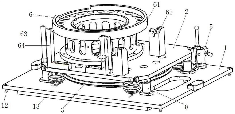
[0048] The difference from Embodiment 1 is that in this embodiment, the above-mentioned anti-rotation structure includes a guide column with a non-circular cross section, such as an ellipse or a square. By making the cross-section of the guide column non-circular, the positioning plate 2 can be prevented from rotating relative to the turntable 3 by its own non-circular cross-section.

Embodiment 3

[0050] The difference between it and Embodiment 1 or Embodiment 2 is that in this embodiment, a runner is also included, and the runner is rotatably installed on the surface of the bottom plate 1, and the runner is rotatable with the bottom plate 1 through the axle and the runner bearing. Connection, such as turntable 3 and base plate 1. The circumferential side wall of the runner is in contact with the circumferential side wall of the turntable 3 . The setting of the runner makes the external drive mechanism, such as the motor installed on the base plate 1, the motor drive the runner to rotate through mechanical connection, and the runner drives the turntable 3 to rotate through friction, compared with the one in the first embodiment. Manual or other ways to realize the rotation of the positioning plate 2, the efficiency of this embodiment is better.

Embodiment 4

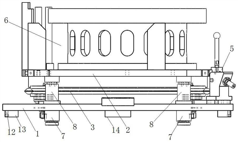
[0052] It differs from Embodiment 1 or Embodiment 2 in that: if Figure 7 and Figure 8 As shown, the present embodiment is similar to Embodiment 3, and a rotatable runner 9 is installed on the surface of the bottom plate 1, and the runner 9 is rotatably connected with the bottom plate 1 through the wheel shaft and the runner bearing, and the circumferential side wall of the runner 9 It is in contact with the circumferential side wall of the turntable 3; but in this embodiment, the number of runners 9 is not less than three, and the three runners 9 are evenly distributed in the circumferential direction. In this embodiment, the preferred runners 9 have four Secondly, in the present embodiment, the contact surface of the runner 9 and the turntable 3 is V-shaped, that is, the circumferential side wall of the runner 9 is provided with an annular groove with a V-shaped opening, and the circumferential side wall of the turntable 3 is set to Inverted V shape cooperates with runner ...


PUM


Abstract

The invention discloses a conveying tray for a transmission assembly line, and belongs to the field of trays. The conveying tray comprises a bottom plate, a turntable and a positioning plate, whereinthe turntable is rotatably mounted on the surface of the bottom plate, the positioning plate is slidably mounted on the surface of the turntable, the sliding direction of the positioning plate is parallel to the rotating axis of the turntable, and a locking mechanism for locking the turntable or the positioning plate is further mounted on the bottom plate; an anti-rotation structure is arranged between the positioning plate and the turntable; a positioning assembly for positioning a transmission is mounted on the surface of the positioning plate; and a jacking mechanism for driving the positioning plate to slide is mounted on the bottom plate. The conveying tray is simple in structure and reasonable in design, and the jacking mechanism is used for jacking up the transmission, so that the operation of detecting and press-fitting the transmission is more stable and accurate; and meanwhile, the rotating function of the transmission is still kept.

Description

technical field [0001] The invention relates to the field of pallets, in particular to a conveying pallet for a transmission assembly line. Background technique [0002] At present, the known assembly conveyor line pallets are all lifted and positioned by the positioning holes on the bottom plate of the jacking pallet. If parts with irregular shapes are encountered, they are positioned by columns; The rotation positioning of the middle turntable and the peripheral runner is adopted. [0003] However, transmissions for heavy-duty new energy vehicles require both flexible rotation directions and precise positioning for inspection and press-fitting in the assembly line. Problems arise when using existing pallets. For example, the positioning hole of the jacking tray positioning bottom plate cannot bring the stable position and attitude of the upper positioning plate of the tray, because there is an uncertain gap between the turntable and the runner due to processing and assemb...

Claims


Application Information

Patent Timeline
Patent Type & Authority Applications(China)
IPC IPC(8): B23P19/00B23P19/02
CPCB23P19/001B23P19/02B23P2700/50
Inventor 刘殿冬
Owner SHANGHAI ZHONGLIAN NENGCHUANG NEW ENERGY TECH CO LTD
Features
  • R&D
  • Intellectual Property
  • Life Sciences
  • Materials
  • Tech Scout
  • Unparalleled Data Quality
  • Higher Quality Content
  • 60% Fewer Hallucinations
Learn More