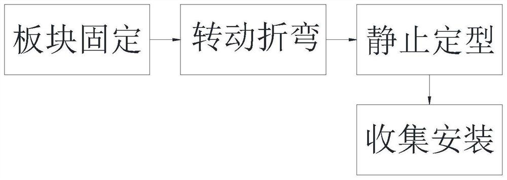
Building decoration material aluminum-plastic plate molding processing method
A technology for building decoration materials and processing methods, which is applied in the field of aluminum-plastic panel preparation, can solve problems such as increased operating costs, troublesome operation, and damage to aluminum-plastic panels, and achieves the goals of controlling the bending angle, improving bending quality, and improving convenience Effect
- Summary
- Abstract
- Description
- Claims
- Application Information
AI Technical Summary
Problems solved by technology
Method used
Image

Examples
Embodiment Construction
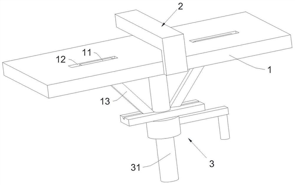
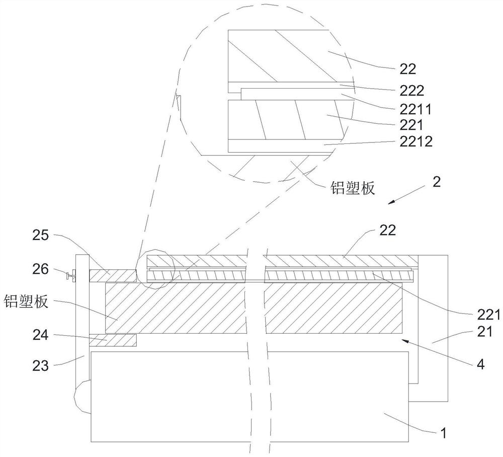
[0033] The present invention will be described in further detail below in conjunction with the accompanying drawings.
[0034] refer to figure 2 As shown, it is a molding processing method of aluminum-plastic panels for building decoration materials disclosed in the present invention. In order to facilitate the bending and adjustment of the angle of the aluminum-plastic panels during actual production, it includes a pair of aluminum-plastic panels for bending adjustment. Bending equipment, the aluminum-plastic plate bending equipment includes a fixed plate 1, the side of the fixed plate 1 is provided with a positioning device 2 for positioning the aluminum-plastic plate, and one side of the fixed plate 1 is rotated and installed to drive the aluminum-plastic plate to bend. drive rod 11, the fixed plate 1 is provided with an embedding groove 12 for the drive rod 11 to be embedded and installed, and the side of the fixed plate 1 far away from the drive rod 11 is fixedly install...
PUM
 Abstract
Description
Claims
Application Information