Eureka AIR delivers breakthrough ideas for toughest innovation challenges, trusted by R&D personnel around the world.

Automatic lens laminator

A technology of laminating machine and laminating mechanism, applied in optics, instruments, other household appliances, etc., can solve the problems of high cost, inconvenience for large-scale use, complex structure, etc. The effect of simplifying the overall structure

Pending Publication Date: 2021-03-26
漳州盈塑工业有限公司
View PDF0 Cites 0 Cited by
  • Summary
  • Abstract
  • Description
  • Claims
  • Application Information

AI Technical Summary

Problems solved by technology

[0003] Aiming at the deficiencies of the prior art, the present invention provides an automatic lens laminating machine, which mainly solves the technical problems that the prior art automatic laminating machine for lenses has a relatively complicated structure, high cost, and is inconvenient to be put into use on a large scale

Method used

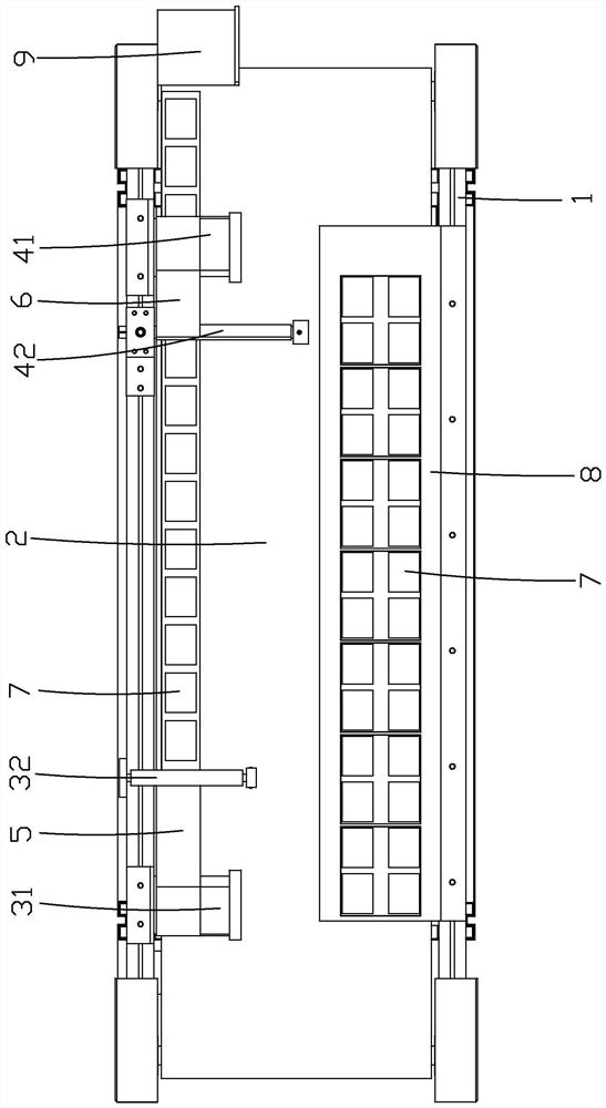
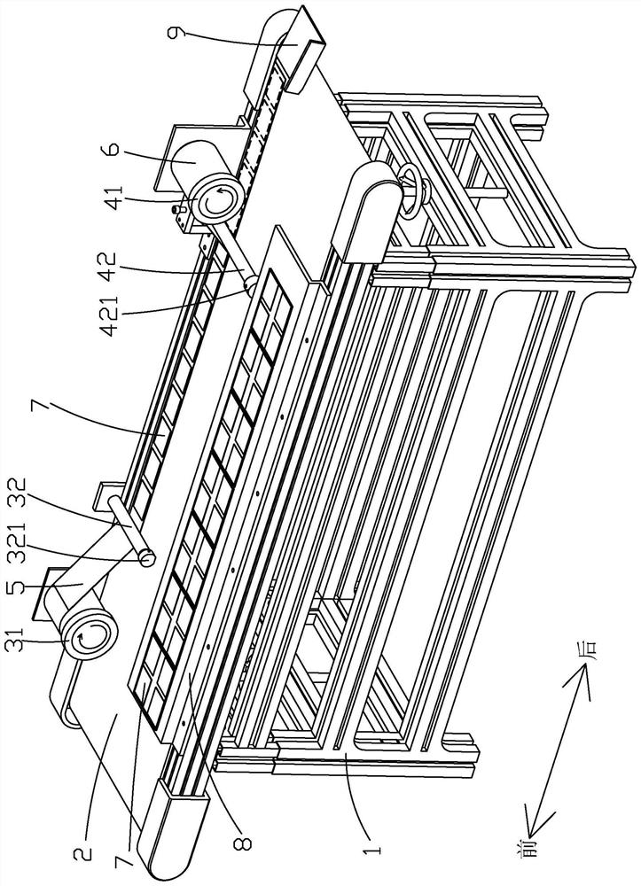
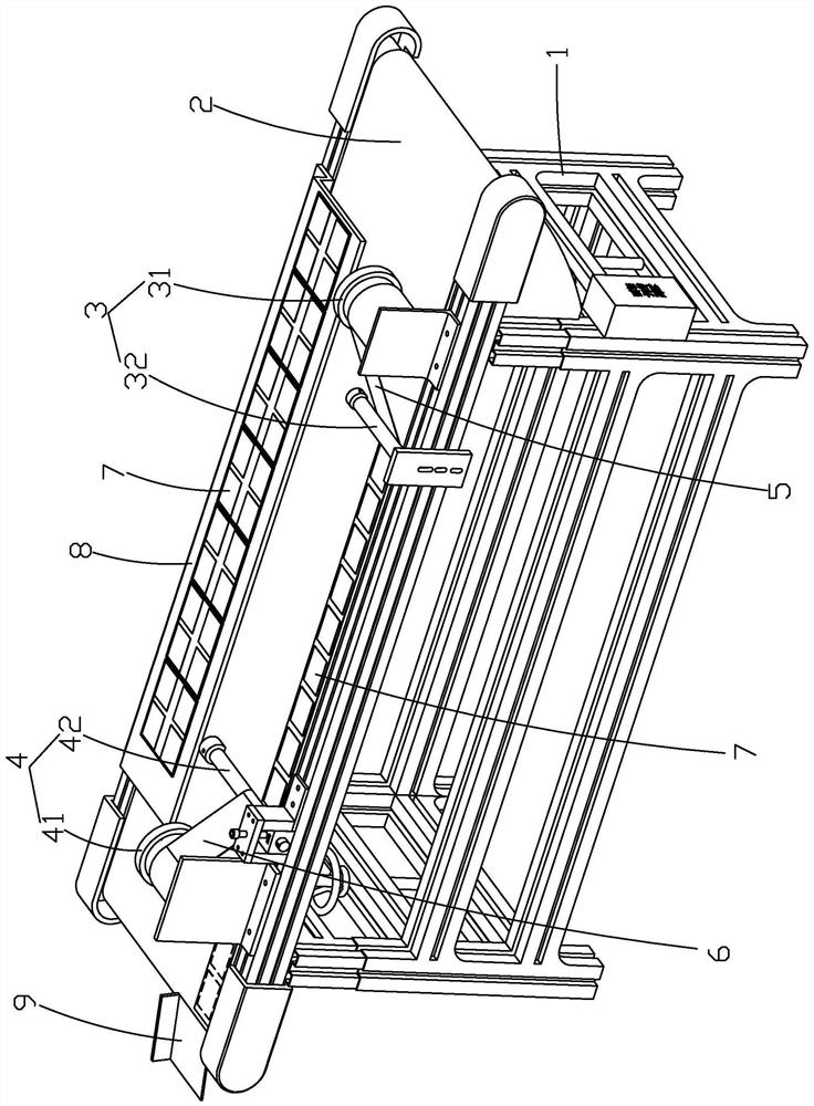

Image

  • Automatic lens laminator
  • Automatic lens laminator
  • Automatic lens laminator

Examples


Embodiment Construction

[0020] The present invention will be further described below in conjunction with the accompanying drawings and embodiments.

[0021] In describing the present invention, it should be understood that the terms "upper", "lower", "front", "rear", "left", "right", "top", "bottom", "inner", " The orientation or positional relationship indicated by "outside", etc. is based on the orientation or positional relationship shown in the drawings, and is only for the convenience of describing the present invention and simplifying the description, rather than indicating or implying that the referred device or element must have a specific orientation, so as to Specific orientation configurations and operations, therefore, are not to be construed as limitations on the invention.

[0022] Please refer to the attached figure 1 to attach image 3 One embodiment of the present invention provides an automatic lens laminating machine, which includes a frame 1, a conveyor belt 2 is provided on the...


PUM


Abstract

The invention discloses an automatic lens laminator which comprises a rack. A conveying belt, a first laminating mechanism and a second laminating mechanism are arranged on the rack, the first laminating mechanism and the second laminating mechanism are correspondingly arranged above the conveying belt, the first laminating mechanism comprises a first carrier roller and a first pressing roller, and the first carrier roller is used for installing a winding drum type lower-layer film; the first pressing roller is configured to be used for pressing the lower-layer film on the conveying belt so that the lower-layer film can synchronously move along with the conveying belt; the second laminating mechanism comprises a second carrier roller and a second pressing roller, and the second carrier roller is used for installing a winding drum type upper-layer film; the second pressing roller is configured to be used for tightly pressing the upper-layer film, the lower-layer film and a lens pre-pasted on the lower-layer film together. According to the automatic laminator, the lower-layer film and the upper-layer film synchronously move along with the conveying belt under the action of friction force, the first laminating mechanism and the second laminating mechanism do not need power devices, the overall structure of the automatic laminator is greatly simplified, the manufacturing cost is reduced, and large-scale application is facilitated.

Description

technical field [0001] The invention relates to the technical field of lens packaging equipment, in particular to an automatic lens laminating machine. Background technique [0002] The lenses of existing electronic equipment are usually packaged with films during the production process to prevent the surface of the lenses from being scratched during transfer or transportation. However, most of the existing automatic lens film laminating machines have complex structures and high costs. It is not convenient for large-scale lens manufacturers to put it into use, but the manual film application method leads to low efficiency of lens film application, which affects the delivery cycle. Contents of the invention [0003] Aiming at the deficiencies of the prior art, the present invention provides an automatic lens laminating machine, which mainly solves the technical problems that the prior art automatic lens laminating machine has a relatively complex structure, high cost, and i...

Claims


Application Information

Patent Timeline
IPC IPC(8): B29C63/02G02B1/10B29L11/00
CPCB29C63/0004B29C63/02B29L2011/0016G02B1/10
Inventor 张发旺朱永文王坤松吕苍娃
Owner 漳州盈塑工业有限公司
Why Eureka
Eureka Blog
Learn More