Roller device for textile machine

A technology for textile machinery and top rollers, which is applied to spinning machines, textiles, papermaking, and drafting equipment. It can solve problems such as inconsistent diameters of top rollers, micro cracks on the surface, and peeling off of the surface treatment layer to reduce replacement and maintenance costs. , Guaranteed working stability, convenient installation and disassembly

Inactive Publication Date: 2021-03-26
温州瓦序鞋业有限公司
View PDF14 Cites 1 Cited by
  • Summary
  • Abstract
  • Description
  • Claims
  • Application Information

AI Technical Summary

Problems solved by technology

[0005] The purpose of the present invention is to provide a roller top roller device for textile machinery, to solve the problem of concave, eccentricity, big and small ends, and two rollers on the same set after the existing roller top roller proposed in the above-mentioned background technology is used for a long time. Problems such as inconsistent diameters of top rollers, fine cracks on the surface, peeling or failure of the surface treatment layer, etc. If the integrated roller top roller is damaged during use, it needs to be replaced as a whole, and the replacement cost is high

Method used


Image

  • Roller device for textile machine
  • Roller device for textile machine
  • Roller device for textile machine

Examples


Embodiment 1

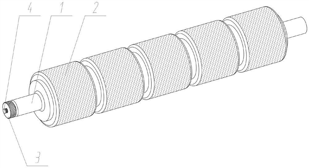
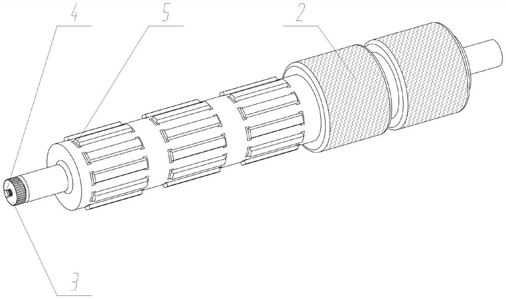
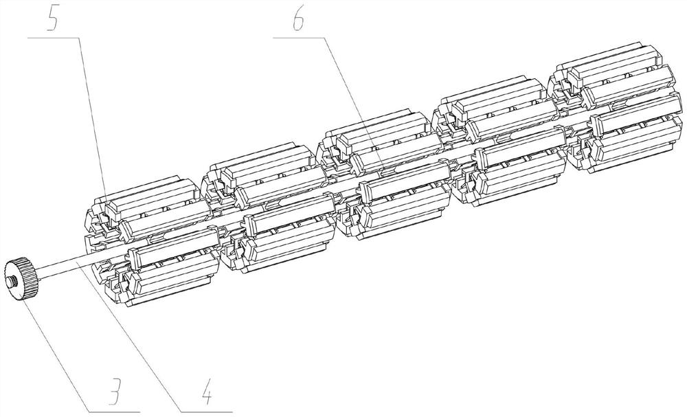
[0032] see Figure 1 to Figure 10 , a roller top roller device for textile machinery, including a roller shaft 1; a group of locking adjustment screw 4 is connected to the center of the roller shaft 1 for rotation; a group of locking operation is slidingly connected to the left end surface of the locking adjustment screw 4 Part 3; the inner sliding connection of the roller shaft 1 has five sets of locking drive blocks 6; the outer circumferential array of the roller shaft 1 is evenly arranged and slidingly connected with locking parts 5; A group of top rollers 2 are connected.

Embodiment 2

[0034] The locking operating part 3 also includes a spline shaft hole 301 and a compression spring 303. A group of spline shaft holes 301 are provided in the middle of the locking operating part 3. The locking adjusting screw 4 also includes a sliding spline shaft 401, A set of sliding spline shafts 401 is coaxially and fixedly connected to the left end face of the locking adjustment screw 4, and the sliding spline shafts 401 are slidably connected to the spline shaft holes 301, and a set of compression springs 303 are arranged on the left side of the locking operation part 3 , the locking operating member 3 is elastically connected to the locking adjusting screw 4 through the compression spring 303 , and in use, the locking operating member 3 is pushed to the right by the compression spring 303 .

Embodiment 3

[0036] The roller shaft 1 also includes locking positioning holes 101, and the left end surface of the roller shaft 1 is arranged in a circumferential array with the locking positioning holes 101. The locking operating part 3 also includes a positioning pin 302, and the right end surface of the locking operating part 3 is fixed. There are two sets of positioning pins 302 connected, and the positioning pins 302 are connected to the locking positioning hole 101. In use, the locking operation part 3 and the roller shaft 1 are realized through the plugging connection of the positioning pins 302 and the locking positioning hole 101. between positioning.


PUM


Abstract

The invention discloses a roller device for a textile machine, relates to the technical field of textile machines, solves the problems that after an existing roller is used for a long time, recesses,eccentricity, big ends and small ends are generated, the diameters of two rollers on a same set are inconsistent, the surfaces of the rollers are finely cracked, surface treatment layers of the rollers are peeled off or loses efficacy and the like, and also solves the problem that the integrated roller needs to be integrally replaced if being damaged in a using process, and the replacement cost ishigh. The integrated roller comprises a roller shaft; wherein the center of the roller shaft is rotationally connected with a set of locking adjusting lead screws; a set of locking operation pieces are connected to the left end face of the locking adjusting lead screw in a sliding mode; and a set of rollers are connected to the outer sides of locking pieces located at the same section position ina tightly-supported mode. By the adoption of the split type roller barrel, part of the roller barrel can be replaced according to the abrasion condition and the deformation condition, the replacementand maintenance cost of the roller is reduced, mounting and dismounting are convenient, looseness of a lead screw nut pair caused by vibration is effectively prevented, and the working stability of the roller is guaranteed.

Description

technical field [0001] The invention relates to the technical field of textile machinery, in particular to a roller top roller device for textile machinery. Background technique [0002] Roller top rollers are often used in the feeding, drafting, and output processes of textile machinery. Roller top rollers are generally iron rods or light rollers covered with elastic materials. The top rollers are composed of top roller cores, top roller iron (steel ) shells, bearings and leather shells, the existing top rollers are generally of an integrated fixed structure. [0003] For example, application number: CN201710917293.3 This patent relates to the field of textile drafting mechanism, discloses a kind of textile roller, comprises rotating roller and receiver, and rotating roller is cylindrical, is coaxially worn with rotating shaft in rotating roller, and the length of rotating shaft is greater than The rotating roller has a mounting hole in the radial direction, a top core is ...

Claims


Application Information

Patent Timeline
Patent Type & Authority Applications(China)
IPC IPC(8): D01H5/74
CPCD01H5/74
Inventor 常忆群
Owner 温州瓦序鞋业有限公司
Why Eureka
Try Eureka