Textile dust collecting device of textile machine for spinning

A technology for dust collection and textile machines, applied in textiles, textiles, papermaking, dryers, etc., can solve problems such as filter blockage, achieve the effects of saving production costs, saving electric energy, and preventing air corrosion

Active Publication Date: 2021-03-26
吴江新生针纺织有限责任公司
View PDF6 Cites 2 Cited by
  • Summary
  • Abstract
  • Description
  • Claims
  • Application Information

AI Technical Summary

Problems solved by technology

[0004] The purpose of the present invention is to solve the problem that the filter screen in the prior art is often blocked, and propose a textile dust collection device for textile machines

Method used


Image

  • Textile dust collecting device of textile machine for spinning
  • Textile dust collecting device of textile machine for spinning
  • Textile dust collecting device of textile machine for spinning

Examples


Embodiment 1

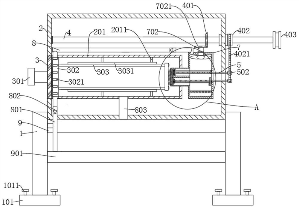
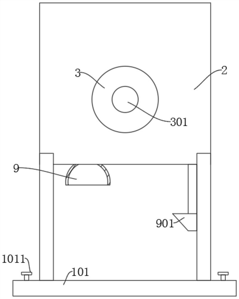
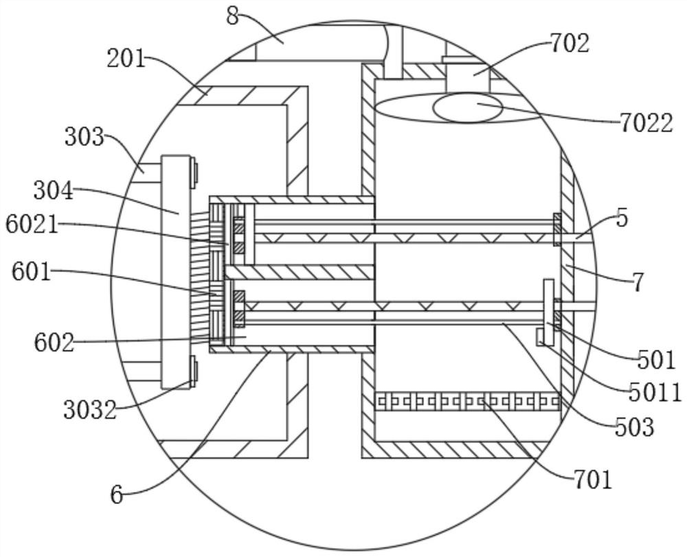
[0029] refer to figure 1 and image 3 , a textile dust collection device for textile machines, comprising a mounting frame 1 and a mounting box 2, the mounting box 2 is fixedly connected to the mounting frame 1, the bottom of the mounting box 2 is fixedly connected with a dust cover 9, and the mounting box 2 is fixed Connected with a storage box 201, the storage box 201 communicates with the dust collection cover 9 through the third air pipe 803, the installation box 2 is fixedly connected with a suction box 7, and the suction box 7 is provided with a suction mechanism, the suction box 7 and the storage box 201 Connected through the filter box 6, the filter box 6 is fixedly connected with a filter screen 601, the filter box 6 is provided with an air inlet hole 602, the air inlet hole 602 is fixedly connected with a mounting plate 6021, and the mounting plate 6021 is rotatably connected with a reciprocating wire Rod 5, the piston plate 501 is threadedly connected to the recipr...

Embodiment 2

[0031] refer to figure 1 and image 3 , is basically the same as Embodiment 1, furthermore, the suction mechanism includes a second gear 7021 and a suction fan 7022, the top of the suction box 7 is rotatably connected to a rotating shaft 702, and the second gear 7021 and the suction fan 7022 are respectively fixedly connected to the rotating shaft The two ends of 702 are fixedly connected with the drive shaft 4 in the installation box 2, and the drive shaft 4 is fixedly connected with the first gear 401, the first sprocket wheel 402 and the connecting wheel 403 from left to right. The first gear 401 Engaging with the second gear 7021, the connecting wheel 403 is rotationally connected with the pulley or sprocket on the spinning machine through the chain 4021 or the belt. When the spinning machine is started, the spinning machine rotates the drive shaft 4 through the connecting wheel 403, The drive shaft 4 rotates the first gear 401 and the first sprocket 402, the first gear 4...

Embodiment 3

[0033] refer to figure 1 and image 3, is basically the same as Embodiment 1, and furthermore, the reciprocating screw rod 5 extends to the outside of the installation box 2 and is fixedly connected with a second sprocket 502, and the second sprocket 502 and the first sprocket 402 are rotatably connected by a chain 4021, and the piston There are two groups of plates 501, two groups of piston plates 501 are symmetrically distributed on two groups of reciprocating screw rods 5, the first sprocket 402 rotates the second sprocket 502 through the chain 4021, and the second sprocket 502 rotates the reciprocating screw rod 5 , so that the piston plate 501 moves back and forth. By providing two sets of piston plates 501, when one set of piston plates 501 enters the air intake hole 602, the other set of piston plates 501 will break away from the air intake hole 602. The wind hole 602 is completely blocked, thereby avoiding causing the dust suction cover 9 to absorb the fluff intermitt...


PUM


Abstract

The invention discloses a textile dust collecting device of a textile machine for spinning, and belongs to the technical field of textile machines. The textile dust collecting device of the textile machine for spinning comprises a mounting frame and a mounting box, wherein the mounting box is fixedly connected to the mounting frame, a dust suction hood is fixedly connected to the bottom of the mounting box, a storage box is fixedly connected in the mounting box, the storage box communicates with the dust suction hood through a third air pipe, an air suction box is fixedly connected in the mounting box, an air suction mechanism is arranged in the air suction box, the air suction box communicates with the storage box through a filter box, a filter screen is fixedly connected in the filter box, an air inlet hole is formed in the filter box, a mounting plate is fixedly connected in the air inlet hole, and a reciprocating lead screw is rotationally connected to the mounting plate. Accordingto the textile duct collecting device, positive ions and negative ions are blown to the filter screen, static electricity on fluff is eliminated, the fluff is blown into the storage box, and therefore the problem that the filter screen is always blocked by the fluff is solved.

Description

technical field [0001] The invention relates to the technical field of textile machines, in particular to a textile dust collection device for textile machines. Background technique [0002] Textile machines are also called textile machines, looms, cotton spinning machines, etc. The ancient textile machines were looms driven by human power. Textile machine is exactly the full name of the tool that processes thread, silk, hemp and other raw materials into silk thread and then weaves it into cloth. Like spinning pendants, spinning wheels, spindles, pedal looms, as well as modern mechanical looms, modern numerical control automatic looms, etc., the development of ancient and modern textile processes and equipment is designed in response to textile raw materials. Plays an important role in textile technology. The fibers used for textiles in ancient countries in the world are all natural fibers, generally wool, hemp, and cotton. At present, a large amount of lint will be produc...

Claims


Application Information

Patent Timeline
Patent Type & Authority Applications(China)
IPC IPC(8): D03J1/00H05F3/06F26B21/00
CPCD03J1/002H05F3/06F26B21/001
Inventor 朱其刚
Owner 吴江新生针纺织有限责任公司
Why Eureka
Try Eureka