
A heat supply control device and control method for a building's thermal inlet

A building and thermal technology, which is applied in the field of thermal inlet heat supply control devices for buildings, can solve the problems of expensive thermal inlet devices, unstable hydraulic conditions of one network, heat waste, etc., and reduce operation and maintenance work. Quantity, stable hydraulic conditions, and the effect of solving high investment costs

Active Publication Date: 2022-03-29
太原大四方节能环保股份有限公司
View PDF4 Cites 0 Cited by
  • Summary
  • Abstract
  • Description
  • Claims
  • Application Information

AI Technical Summary

Problems solved by technology

[0004] If the heat source supplies heat to dozens or even hundreds of heat exchange stations, it is difficult to meet the different needs of heat users in each heat exchange station with a unified heat source outlet temperature, especially the demand for real-time heat load changes. A certain heat user in a heat station needs to increase the outlet water temperature of the heat source, which will cause a huge waste of heat; the regulation at the heat exchange station is much better, and the water supply temperature of each heat exchange station is only responsible for meeting the heat supply of the area it supplies. Even if the control effect is not good, the scope of its influence is limited to the heating area of ​​the heat exchange station; although the control effect of the heat exchange station is better than that of the heat source, the imbalance problem of the second network has not been solved, and the independent control process of the heat exchange station From the perspective of the smaller the control range, the more energy-saving, household metering is the best way to regulate heat supply, and the scope of regulation is a family, but household metering is due to various problems If it is not used, a set of heat entry devices for each household is expensive, resulting in a huge investment

Method used


Image

  • A heat supply control device and control method for a building's thermal inlet

Examples


Embodiment Construction

[0038] The present invention will be further described below in conjunction with the accompanying drawings.

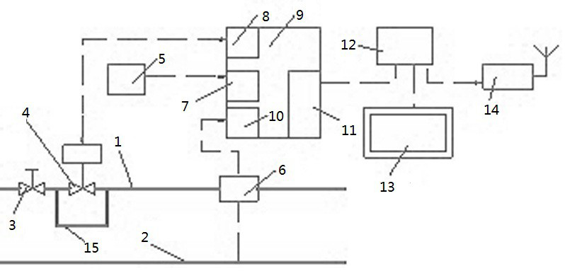
[0039] Such as figure 1 As shown, a thermal inlet heat supply control device of a building includes a thermal inlet water supply pipe 1, a thermal inlet return pipe 2, a water supply bypass pipe 15, a V-shaped ball valve 3, an electric two-way valve 4, a room temperature sensor 5, and a heat Table 6. Programmable controller 9, router 12, touch screen 13 and gateway 14; programmable controller PLC 9 is equipped with RS485 interface 7. RS485 interface 10. On-off interface 8 and network interface 11, V-shaped ball valve 3, electric two-way valve 4 and heat meter 6 are arranged in turn on the heat inlet water supply pipe 1, and the two ends of the electric two-way valve 4 are connected to the water supply bypass pipe 15; RS485 interface 7 Connect to room temperature sensor 5, RS485 interface 10 is connected to the heat meter 6, the switch interface 8 is connected ...


PUM


Abstract

The invention belongs to the technical field of heating, ventilating and air conditioning, and specifically relates to a heat supply regulating device and a regulating method of a thermal entrance of a building. The involved device includes a programmable controller PLC, a room temperature sensor, a heat meter, an electric two-way valve and a network interface. The heat supply area of ​​the heat supply area of ​​the heat entrance can be controlled at the heat entrance of the building or the heat entrance of the building unit according to the heat load, so as to realize on-demand heat supply. The two heat supply control methods mentioned above are: one is The other is the constant temperature control method, and the other is the fixed return temperature control method. Both of these methods avoid complex heat load forecasting algorithms. The range is small, and the hysteresis is also small, and its control is more targeted and more energy-saving.

Description

technical field [0001] The invention belongs to the technical field of heating, ventilating and air-conditioning, and in particular relates to a device and method for regulating heat supply at a thermal inlet of a building. Background technique [0002] The heat supply of the central heating system cannot be adjusted according to demand, which has long plagued thermal power companies and has not been effectively resolved. There are many reasons, but the main reasons are inaccurate heat load prediction and hydraulic dynamic imbalance of the pipe network. [0003] From the perspective of the heating system, heat supply regulation can be carried out in any link of heat source, heat exchange station, building heat entrance, building unit heat entrance, and heat user. The heat station regulation is the joint regulation of the quality of the two networks, and the regulation at the heat user is the household metering. Now the most used regulation method is heat source concentration...

Claims


Application Information

Patent Timeline
Patent Type & Authority Patents(China)
IPC IPC(8): F24D19/10F24D3/10
CPCF24D19/1015F24D19/1048F24D3/1058F24D2220/042
Inventor 夏路易胡庆彦
Owner 太原大四方节能环保股份有限公司
Learn More