
Remote monitoring method for mine power supply and distribution system

A power supply and distribution system, remote monitoring technology, applied in the direction of circuits, electric switches, electrical components, etc., can solve problems such as difficulty in meeting the needs of mine circuits, slow action of spring operating mechanisms, and inability to quickly remove faults, etc., to reduce arcing Existence time, prevent safety accidents, and reduce the effect of severe ablation

Inactive Publication Date: 2021-03-26
孙云飞
View PDF0 Cites 2 Cited by
  • Summary
  • Abstract
  • Description
  • Claims
  • Application Information

AI Technical Summary

Problems solved by technology

[0006] In order to make up for the deficiencies of the existing technology and solve the problem that the existing spring operating mechanism moves slowly and cannot quickly remove faults, which makes it difficult to meet the use requirements of mine circuit power supply and distribution monitoring, a mine power supply and distribution mechanism proposed by the present invention Electric system remote monitoring method

Method used

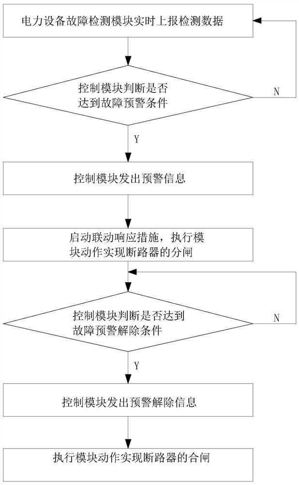
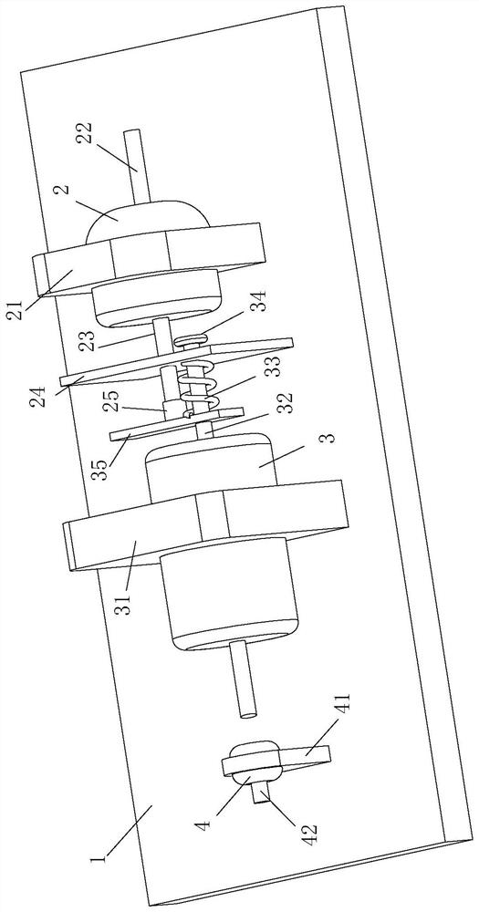
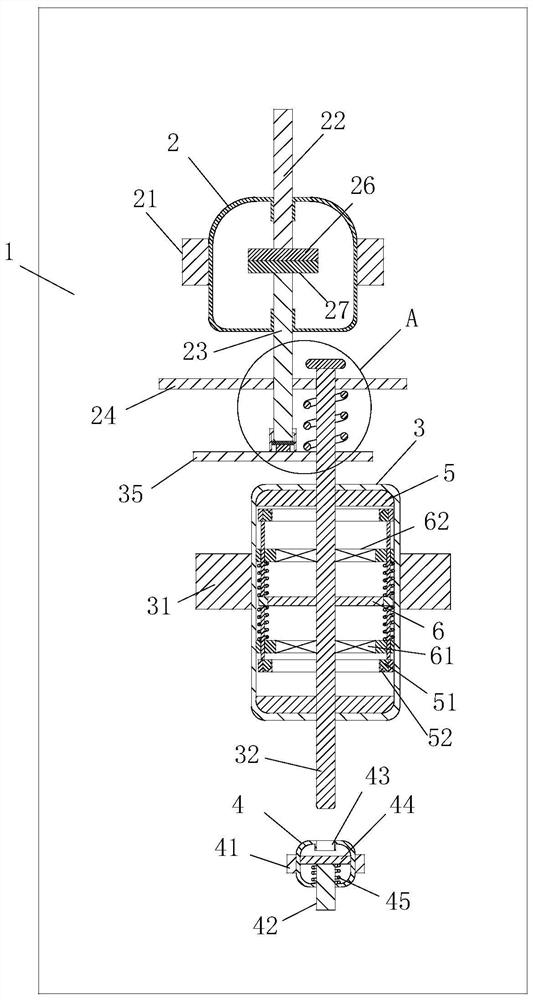

Image

  • Remote monitoring method for mine power supply and distribution system
  • Remote monitoring method for mine power supply and distribution system
  • Remote monitoring method for mine power supply and distribution system

Examples


Embodiment approach

[0042] As an embodiment of the present invention, a damping block 29 is provided between the lower end of the slider 28 and the bottom of the inner cavity of the sleeve 25 . Through the setting of the damping block 29, the impact energy of the push plate 35 can be consumed through its own deformation after the movable contact 27 contacts the static contact 26, so as to achieve the purpose of shock absorption and buffering, and avoid the impact of the movable contact due to excessive impact force. 27 Closing failure caused by too large bouncing; at the same time, it also reduces the impact force of the moving contact on the static contact, avoids the coarse deformation of the static contact pier, and further improves the success rate of closing.

[0043] As an embodiment of the present invention, the outer circumference of the first coil 61 and the second coil 62 is provided with a first annular plate 63, and the outer side of the first annular plate 63 is fixedly connected with...


PUM


Abstract

The invention relates to the technical field of power supply and distribution monitoring, in particular to a remote monitoring method for a mine power supply and distribution system. A circuit breakerused in the method comprises a vertically-arranged mounting plate, and a vacuum arc-extinguishing device and an operation maintaining device are sequentially arranged on the front side of the mounting plate from top to bottom; the vacuum arc-extinguishing device comprises an arc-extinguishing chamber, the arc-extinguishing chamber is fixed on a mounting plate through a first fixing frame on the outer side of the arc-extinguishing chamber, a static contact is fixedly arranged on the upper portion of the arc-extinguishing chamber, and the upper end of the static contact is connected with a static conducting rod extending out of the upper end of the arc-extinguishing chamber. The upper part and the lower part of the arc- extinguishing chamber is provided with moving contacts which are rightopposite to the static contact. Through arrangement of an eddy current disc, a first coil and a second coil, rapid separation of the moving contact and the static contact is realized through an electromagnetic repulsion mode, and compared with a spring type separation mode, rapid opening of the circuit breaker is realized so that faults can be rapidly removed, occurrence of safety accidents can beprevented and use requirements of ore circuit power supply and distribution monitoring can be met.

Description

technical field [0001] The invention relates to the technical field of electric power supply and distribution monitoring, in particular to a remote monitoring method for a mine power supply and distribution system. Background technique [0002] In production and life, the power supply and distribution system provides three-phase power supply to various power consumption facilities, and each circuit is controlled through the distribution box. For example, the control of the lighting circuit needs to change according to the season and time, and adjust the lighting time. And turn off the lights when not needed to save energy. The traditional power supply and distribution system has simple equipment and control, low degree of automation, and requires special personnel on duty and patrolling. If a fault occurs, it needs to be searched along the line, which cannot meet the needs of the rapid development of modern society and economy. [0003] The circuit breaker is an indispensab...

Claims


Application Information

Patent Timeline
Patent Type & Authority Applications(China)
IPC IPC(8): H01H33/666H01H3/60H02J13/00
CPCH01H3/60H01H33/666H02J13/00002H02J13/00036
Inventor 孙云飞张卫滨张忠华
Owner 孙云飞
Learn More