Combined connector

A technology of connectors and connecting sleeves, which is applied in the direction of connecting, joining/disconnecting connected parts, two-part connecting devices, etc., which can solve the problems of large tolerance range, high mating precision, and large volume of high-current connectors. To achieve the effect of ensuring reliability

Active Publication Date: 2021-03-26
SICHUAN HUAFENG ENTERPRISE GRP
View PDF8 Cites 1 Cited by
  • Summary
  • Abstract
  • Description
  • Claims
  • Application Information

AI Technical Summary

Problems solved by technology

In the traditional way, it is necessary to use different types of connectors to conduct different electrical signals, which are divided into categories. The types of connectors used are various, the number is large, and the cost is high.
At the same time, the equipment itself requires a large installation space, and the size, shape, and installation method of the connectors are different, which affects the overall appearance of the equipment.
[0003] Traditional high-current connectors are not compatible with shielded signal connectors
First, high-current connectors are bulky, and when plugs and sockets are mated, the alignment accuracy is low and the allowable tolerance range is large; signal connectors with shielding treatment require high mating accuracy
Second, the size of the contact end of the contact piece of the high-current connector is relatively large, and the size of the contact end of the contact piece of the signal connector is small. During the mating process, the contact parts of signal connectors are prone to be bent

Method used


Image

  • Combined connector
  • Combined connector
  • Combined connector

Examples


Embodiment Construction

[0039] In order to make the purpose, technical solutions and advantages of the embodiments of the present invention clearer, the technical solutions in the embodiments of the present invention will be clearly and completely described below in conjunction with the accompanying drawings in the embodiments of the present invention. Obviously, the described embodiments It is some embodiments of the present invention, but not all of them. The components of the embodiments of the invention generally described and illustrated in the figures herein may be arranged and designed in a variety of different configurations.

[0040] Accordingly, the following detailed description of the embodiments of the invention provided in the accompanying drawings is not intended to limit the scope of the claimed invention, but merely represents selected embodiments of the invention. Based on the implementation manners in the present invention, all other implementation manners obtained by persons of or...


PUM


Abstract

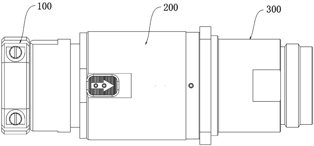
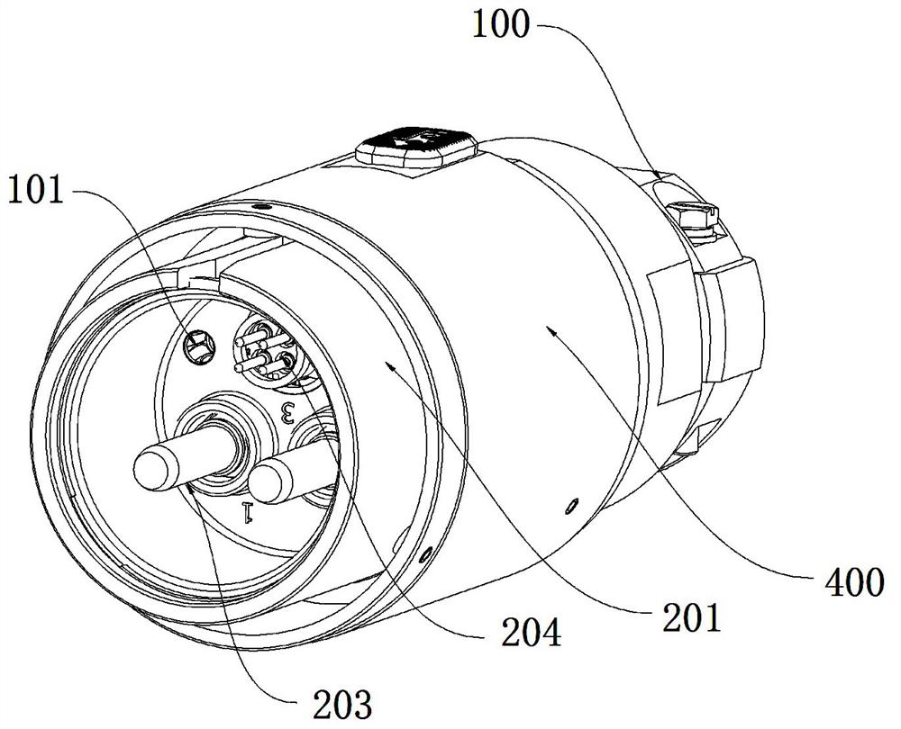
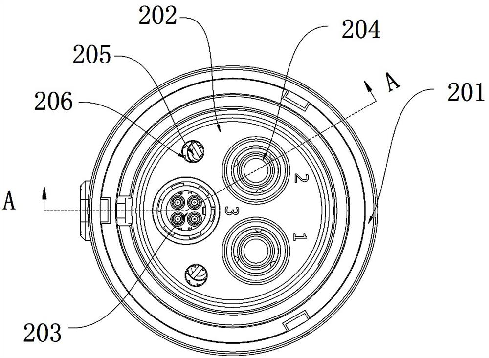
The invention discloses a combined connector. An installation plate a is installed in a shell a, a stepped hole is further formed in the installation plate a, the stepped hole is located in one side of a signal pin assembly, a spring ring is installed in the stepped hole, a connecting sleeve assembly is further installed on the shell a in a sleeving mode, a clamping nail is arranged on the connecting sleeve assembly, a socket comprises a shell b, and an installation plate b is installed in the shell b. A positioning rod is arranged on the installation plate b, after the plug is inserted into the socket, the positioning rod is inserted into the spring ring, and the clamping nail is located at the bottom of the spiral groove. When the plug and the socket are plugged, the spring ring and thepositioning rod can be combined to form second floating positioning, thereby realizing flexible and accurate positioning of the connector, and ensuring that the signal pin assembly and the signal jackassembly are not easy to bend in the plugging process. And the connecting sleeve assembly has an anti-reverse function, the shell can only rotate in one direction, so that the connection reliabilityof the socket and the plug is ensured, and the connecting sleeve assembly can be unlocked by axially moving the sliding part, so that the separation of the socket and the plug is realized.

Description

technical field [0001] The invention relates to a connector, in particular to a combined connector. Background technique [0002] With the rapid development of industry, modern automation equipment covers more and more functions, and the requirements for automation equipment are also getting higher and higher. In a device, it is necessary to conduct high current connectors such as power supply and power supply, as well as small current connectors capable of conducting signal types with shielding treatment. In the traditional way, it is necessary to use different types of connectors to conduct different electrical signals, which are divided into different categories. The types of connectors used are various, the number is large, and the cost is high. At the same time, the equipment itself requires a large installation space, and the size, shape, and installation method of the connectors are different, which affects the overall appearance of the equipment. [0003] Tradition...

Claims


Application Information

Patent Timeline
Patent Type & Authority Applications(China)
IPC IPC(8): H01R13/631H01R13/64H01R13/514H01R13/62H01R24/00
CPCH01R13/6315H01R13/64H01R13/514H01R13/62H01R24/00
Inventor 蒋芳芳李圣强
Owner SICHUAN HUAFENG ENTERPRISE GRP
Why Eureka
Try Eureka