Eureka AIR delivers breakthrough ideas for toughest innovation challenges, trusted by R&D personnel around the world.

Ventilation and heat dissipation structure of active electric power metering box

A power metering box, ventilation and heat dissipation technology, applied in the cooling/ventilation of substation/switchgear, electrical components, substation/distribution device casing, etc., can solve the problems of poor heat dissipation effect, complex structure, low practicability, etc.

Pending Publication Date: 2021-03-26
国网天津市电力公司营销服务中心 +2
View PDF0 Cites 0 Cited by
  • Summary
  • Abstract
  • Description
  • Claims
  • Application Information

AI Technical Summary

Problems solved by technology

[0004] Aiming at the deficiencies of the prior art, the present invention provides an active ventilation and heat dissipation structure of the electric power metering box to solve the problem that in the prior art, the inside of the electric energy metering box is in a closed state, and the large amount of heat generated after the electrical equipment works for a long time makes the electric energy metering The temperature in the box rises suddenly, which may easily cause the components to burn out or even cause a fire, which is harmful to people's personal safety and property safety. Low efficiency, the traditional power metering box has complex structure, inconvenient use, no heat dissipation effect, and when the rainy season comes, rainwater is easy to corrode the power metering box, poor waterproof performance, and low practicability technical problems

Method used


Image

  • Ventilation and heat dissipation structure of active electric power metering box
  • Ventilation and heat dissipation structure of active electric power metering box
  • Ventilation and heat dissipation structure of active electric power metering box

Examples


Embodiment Construction

[0019] Embodiments of the present invention are described in further detail below in conjunction with the accompanying drawings:

[0020] see Figure 1 to Figure 4 , the present invention provides a technical solution:

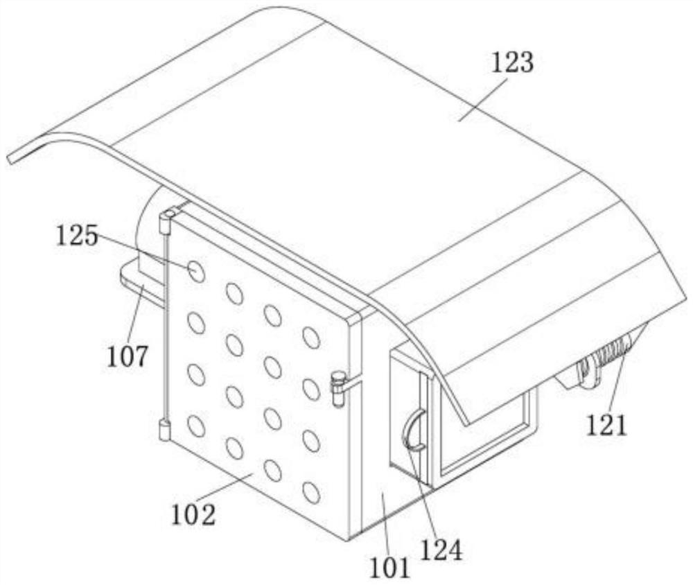
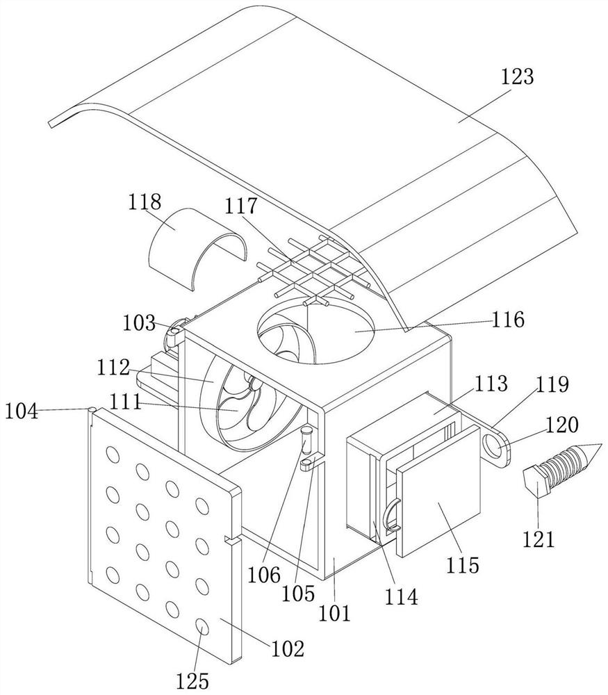
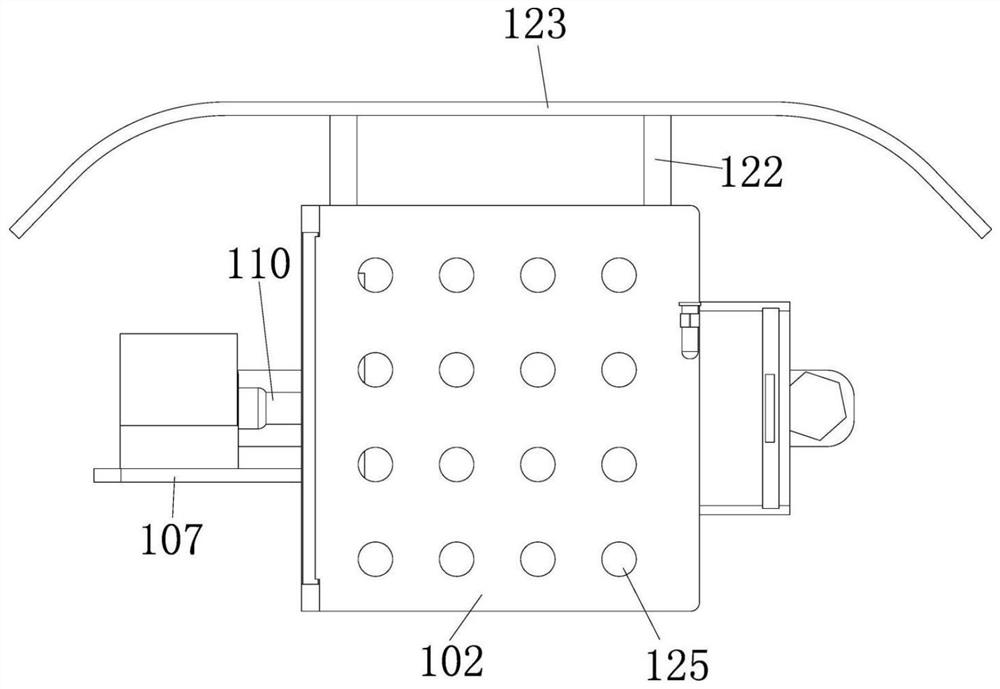
[0021] An active power metering box ventilation and heat dissipation structure, comprising a box body 101, the box body 101 is provided with a box door 102, and the box door 102 is provided with a plurality of groups of ventilation holes 125, and the box door 102 is provided with Connecting pin 104, described connecting pin 104 is connected with described box body 101 through connecting seat 103; Described box body 101 and described box door 102 joints are provided with fixing seat 105, and described fixing seat 105 is provided with fixing seat 105. Pin 106; one side of the box body 101 is provided with a support plate 107, the support plate 107 is provided with a support seat 108, the support seat 108 is provided with a motor 109, and the motor 109 is provid...


PUM


Abstract

The invention discloses a ventilation and heat dissipation structure of an active electric power metering box. The structure comprises a box body, a box door is arranged on the box body, a plurality of groups of ventilation holes are formed in the box door, and a connecting pin is arranged on the box door. A fixed seat is arranged at the joint of the box body and the box door, and a fixed pin is arranged on the fixed seat; a supporting plate is arranged on one side of the box body, a supporting seat is arranged on the supporting plate, a motor is arranged on the supporting seat, a rotating shaft is arranged on the motor, and ventilation fan blades are arranged on the rotating shaft; an exhaust box is arranged on the other side of the box body, and an adjusting mechanism is arranged in theexhaust box. An installation hole is formed in the box body, and a dustproof net is arranged in the installation hole. The ventilation holes are formed, the structure is simple, use is convenient, andthe ventilation and heat dissipation effects are improved; ventilation fan blades are arranged, and the ventilation fan blades rotate to discharge heat generated in the box body; the adjusting mechanism is arranged, the adjusting mechanism closes the exhaust box in rainy seasons, rainwater is prevented from entering, and the waterproof performance is improved; a dust screen is arranged, so that alarge amount of dust is prevented from entering the box body, and the ventilation effect is reduced.

Description

technical field [0001] The invention belongs to the field of metering equipment, and relates to a metering box, in particular to an active power metering box ventilation and heat dissipation structure. Background technique [0002] Power metering box is a device used for electric energy metering in 3~35kv, including combined transformer (collecting three-phase current and voltage signals), box body, watt-hour meter, lightning arrester, vacuum circuit breaker (prepaid type), etc. ;Because there are multiple electrical equipment installed in the electric energy metering box, the electrical equipment will generate heat when it is working, especially in summer, no matter indoors or outdoors, the inside of the electric energy metering box is in a closed state, and the large amount of heat generated by the electrical equipment after working for a long time makes the The temperature in the electric energy metering box rises suddenly. If the heat is not dissipated in time, it will e...

Claims


Application Information

Patent Timeline
Patent Type & Authority Applications(China)
IPC IPC(8): H02B1/46H02B1/56H02B1/28
CPCH02B1/46H02B1/565H02B1/28
Inventor 刘春雨王月明葛春萌张志龙王维光张文婷王首堃戴睿
Owner 国网天津市电力公司营销服务中心
Why Eureka
Eureka Blog
Learn More