Batch type circulating grain drying granary with multi-stage moisture removal and heat dissipation structure

A heat-dissipating structure and grain drying technology, applied in the direction of preservation of seeds by drying, agricultural machinery and implements, botanical equipment and methods, etc. The effect of water vapor return

Inactive Publication Date: 2021-03-30
湖北盛琪达工程科技有限公司
View PDF7 Cites 3 Cited by
  • Summary
  • Abstract
  • Description
  • Claims
  • Application Information

AI Technical Summary

Problems solved by technology

[0002] The storage of grain must be dried to safe moisture to be safer, but the drying of Kuisu can only dry the water and moisture on the surface of the grain, and the internal combination will not change the content due to rapid drying, so during the storage process It is also necessary to carry out drying treatment to prevent the grain from regaining moisture and heat and cause losses. Most of the existing granaries are closed granaries. After the grain is stored, it will not be processed, which may cause damage to the grain and cause losses.

Method used


Image

  • Batch type circulating grain drying granary with multi-stage moisture removal and heat dissipation structure
  • Batch type circulating grain drying granary with multi-stage moisture removal and heat dissipation structure
  • Batch type circulating grain drying granary with multi-stage moisture removal and heat dissipation structure

Examples


Embodiment Construction

[0023] The following will clearly and completely describe the technical solutions in the embodiments of the present invention with reference to the accompanying drawings in the embodiments of the present invention. Obviously, the described embodiments are only some, not all, embodiments of the present invention. Based on the embodiments of the present invention, all other embodiments obtained by persons of ordinary skill in the art without making creative efforts belong to the protection scope of the present invention.

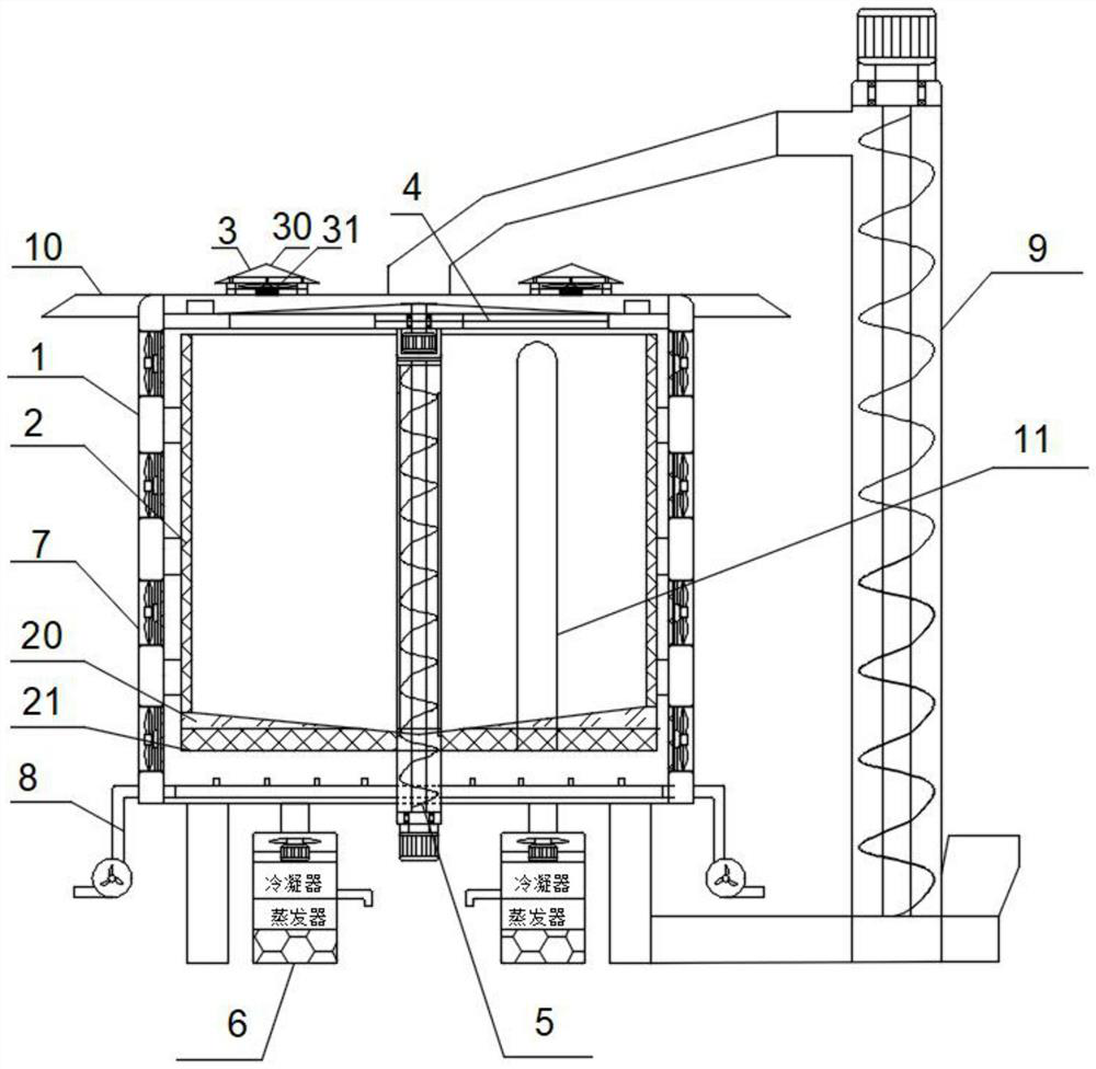
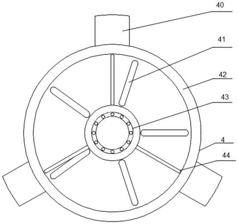
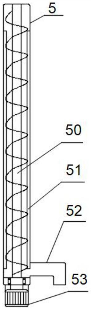
[0024] see Figure 1~5 , in an embodiment of the present invention, a batch-type circulating grain drying granary with a multi-stage dehumidification and heat dissipation structure includes a granary outer box 1, a grain storage tank 2, a heat dissipation component 3, a grain sprinkler component 4, a grain output component 5, Dry air intake assembly 6, dehumidification fan 7, blower 8, grain feeding assembly 9, the granary outer box 1 is supported and fixed ab...


PUM


Abstract

The invention discloses a batch type circulating grain drying granary with a multi-stage moisture removal and heat dissipation structure. The batch type circulating grain drying granary comprises a granary outer box body, a grain storage tank, two groups of heat dissipation assemblies, a grain throwing assembly, a grain outlet assembly, a dry air inlet assembly, a dehumidification fan, an air blower and a grain inlet assembly, wherein the granary outer box body is supported and fixed above the ground through a bracket; the grain storage tank is located in the granary outer box body and fixedlyconnected to the inner wall of the granary outer box body through a bracket, and the two groups of heat dissipation assemblies are located at the upper end of the granary outer box body, symmetrically arranged relative to a feeding port of the granary, fixedly connected to the top end of the granary outer box body and communicate with the interior of the box body; and the grain throwing assemblyis located at the top end of the grain storage tank and fixedly connected to the inner wall of the granary outer box body, the upper end of the grain outlet assembly is fixedly connected with the middles of the bottom ends of the heat dissipation assemblies, the bottom end of the grain outlet assembly extends out of the bottom of the granary outer box body, and the periphery of the bottom end of the grain outlet assembly is fixedly connected with the bottom wall of the granary outer box body.

Description

technical field [0001] The invention relates to the technical field of grain storage devices, in particular to a batch-type circulating grain drying granary with a multi-stage moisture-discharging and heat-dissipating structure. Background technique [0002] The storage of grain must be dried to safe moisture to be safer, but the drying of Kuisu can only dry the water and moisture on the surface of the grain, and the internal combination will not change the content due to rapid drying, so during the storage process It is also necessary to carry out drying treatment to prevent losses caused by resurgence and heating of grains. Most of the existing granaries are closed granaries. After the grains are stored, they are not processed, which may cause damage to the grains and cause losses. Contents of the invention [0003] The object of the present invention is to provide a batch-type circulating grain drying granary with a multi-stage moisture-discharging and heat-dissipating ...

Claims


Application Information

Patent Timeline
Patent Type & Authority Applications(China)
IPC IPC(8): A01F25/14A01F25/22A23B9/08
CPCA01F25/14A01F25/22A23B9/08
Inventor 李晓颖石林
Owner 湖北盛琪达工程科技有限公司
Why Eureka
Try Eureka