Dispensing compensation system and compensation method based on glue flow detection

A flow detection and compensation system technology, applied in the field of dispensing compensation, can solve the problems that the glue volume cannot be accurately weighed, the glue is easy to stick to the needle, and the weighing method is not ideal, so as to achieve stable compensation of glue, Good market application value, the effect of improving debugging efficiency and accuracy

Active Publication Date: 2021-03-30
SHENZHEN AXXON AUTOMATION
View PDF11 Cites 3 Cited by
  • Summary
  • Abstract
  • Description
  • Claims
  • Application Information

AI Technical Summary

Problems solved by technology

[0002] With the development of industry and technology, various industries have higher and higher requirements for dispensing technology. The main performance is that the line width of dispensing is getting more and more extreme, and the control of glue volume is getting smaller and more stable, which leads to the dispensing glue required by the equipment. Heavy control is becoming more and more precise. At the same time, with the popularization of industrial automation, a series of module optimization of equipment must be designed around the core of fully automatic unmanned intervention, and due to the curing of the glue on the inner wall of the dispensing needle and the viscosity of the glue Changes will lead to changes in the glue output of the dispensing needle, so human intervention is often required to adjust the dispensing control system. At present, in the dispensing industry, the way to monitor the glue volume is mainly through the weighing module. Weigh the weight of the glue dispensed per unit time, and then adjust the dispensing speed, but because of the needle dispensing process, the weighing method is not ideal, because the glue is easy to stick to the needle, resulting in the amount of glue not being accurately weighed. , and an error occurs

Method used


Image

  • Dispensing compensation system and compensation method based on glue flow detection
  • Dispensing compensation system and compensation method based on glue flow detection
  • Dispensing compensation system and compensation method based on glue flow detection

Examples


Embodiment 1

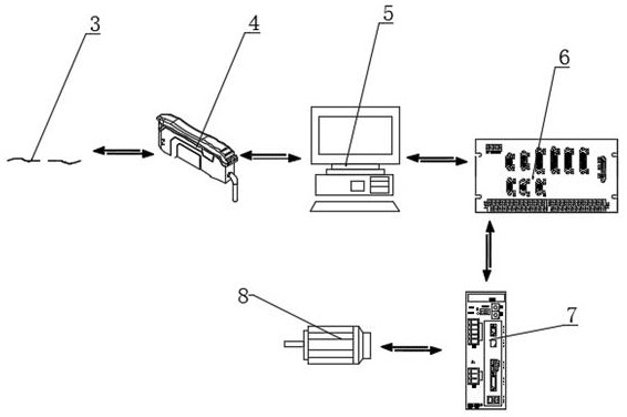
[0035] Such as Figure 1 to Figure 5 As shown, Embodiment 1 of the present invention: a dispensing compensation system based on glue flow detection, including a glue receiving mechanism, a fixing seat 1, an optical fiber sensor 3, an amplifier 4, a PC industrial computer 5, a driver 7 and dispensing execution Motor 8, the fixed seat 1 is arranged directly below the dispensing needle of the dispensing equipment, the material receiving mechanism is arranged at the middle and upper part of the fixed seat 1, and the optical fiber sensor 3 is arranged at the upper part of the fixed seat 1 And located directly above the material receiving mechanism, the optical fiber sensor 3 is connected to the amplifier 4 through a connecting line, the amplifier 4 is connected to the PC industrial computer 5 through a connecting line, and the PC industrial computer 5 is connected to the The driver 7 is connected through a connection line, the driver 7 is connected with the dispensing execution mot...


PUM


Abstract

The invention discloses a dispensing compensation system and compensation method based on glue flow detection. The dispensing compensation system comprises a glue receiving mechanism, a fixed seat, anoptical fiber sensor, an amplifier, a PC industrial personal computer, a driver and a dispensing execution motor. The fixed seat is arranged under a dispensing needle of dispensing equipment, the receiving mechanism is arranged on the middle upper portion of the fixed seat, the optical fiber sensor is arranged on the upper portion of the fixed seat and located over the receiving mechanism, the optical fiber sensor is connected with the amplifier through a connecting wire, the driver is connected with the dispensing execution motor through a connecting wire, and the dispensing execution motoris connected with a driving shaft of the dispensing equipment. The proportional value of dripping speed changes is automatically calculated according to different dripping speeds, the speed or air pressure of a dispensing control system is automatically adjusted in an equal proportion, the effect of stably compensating glue is achieved, the compensation technology is stable, the debugging efficiency and accuracy are improved, and good market application value is achieved.

Description

technical field [0001] The invention relates to the technical field of dispensing compensation, in particular to a dispensing compensation system and compensation method based on glue flow detection. Background technique [0002] With the development of industry and technology, various industries have higher and higher requirements for dispensing technology. The main performance is that the line width of dispensing is getting more and more extreme, and the control of glue volume is getting smaller and more stable, which leads to the dispensing glue required by the equipment. Heavy control is becoming more and more precise. At the same time, with the popularization of industrial automation, a series of module optimization of equipment must be designed around the core of fully automatic unmanned intervention, and due to the curing of the glue on the inner wall of the dispensing needle and the viscosity of the glue Changes will lead to changes in the glue output of the dispensi...

Claims


Application Information

Patent Timeline
Patent Type & Authority Applications(China)
IPC IPC(8): B05C5/02B05C11/10
CPCB05C5/02B05C11/10B05C11/1039Y02P90/02
Inventor 张建华徐维万杨波
Owner SHENZHEN AXXON AUTOMATION
Why Eureka
Try Eureka