Plate cutting machine for space flight and aviation

A technology of aerospace and trigger, which is applied to machine tools suitable for grinding workpiece edges, parts of grinding machine tools, metal processing machinery parts, etc., and can solve problems such as high smoothness requirements, time-consuming and labor-intensive problems

Inactive Publication Date: 2021-03-30
罗火云
View PDF0 Cites 0 Cited by
  • Summary
  • Abstract
  • Description
  • Claims
  • Application Information

AI Technical Summary

Problems solved by technology

[0008] The present invention provides a board cutting machine for aerospace through improvement. The third motor drives the second transmission shaft to rotate through the coupling in the forward direction, the second transmission shaft drives the third gear to rotate, and the third gear drives the front gear while rotating forward. Rotate with the rear gear, the rear gear will rotate in the opposite direction, then the front gear and the rear gear drive the inner diameter shaft and the second shaft to rotate at the same time, the shaft and the second shaft drive the outer diameter emery roller and the second emery roller to rotate at high speed, the left end of the shaft is inserted The pulley assembly is connected, and the built-in pulley of the pulley assembly is plugged with the rotating shaft and the built-in rotating shaft of the third emery roller at the same time. The rotating shaft drives the pulley assembly to revolve around the inner diameter of the second belt, and drives the pulley assembly to drive the third emery roller to rotate forward , the emery roller, the second emery roller and the third emery roller rotate to convey the inner diameter of the right end and grind and deburr the surface of the profile plate. The emery roller, the second emery roller and the third emery roller are conducive to complete grinding of the profile plate The beneficial effect of polishing solves the problem of high requirements on the surface smoothness of the profile plate during the use of ordinary equipment, and often requires manual secondary processing after processing, resulting in time-consuming and labor-intensive problems; hold the rotating rod by hand before use, and then turn it The rod rotates in the opposite direction and drives the screw to rotate. Since the screw is threaded with the nut column, the screw moves upward. The left side of the bottom end of the screw is inlaid with the pin shaft. Drive the third emery roller to lift up, which is beneficial to adjust the vertical height of the third emery roller and the second emery roller, so that the third emery roller and the second emery roller can fit the profile plate better, and solve the problem that ordinary equipment cannot adjust the height Adjustment, resulting in the grinding of a single profile, the problem of poor applicability

Method used


Image

  • Plate cutting machine for space flight and aviation
  • Plate cutting machine for space flight and aviation
  • Plate cutting machine for space flight and aviation

Examples


Embodiment Construction

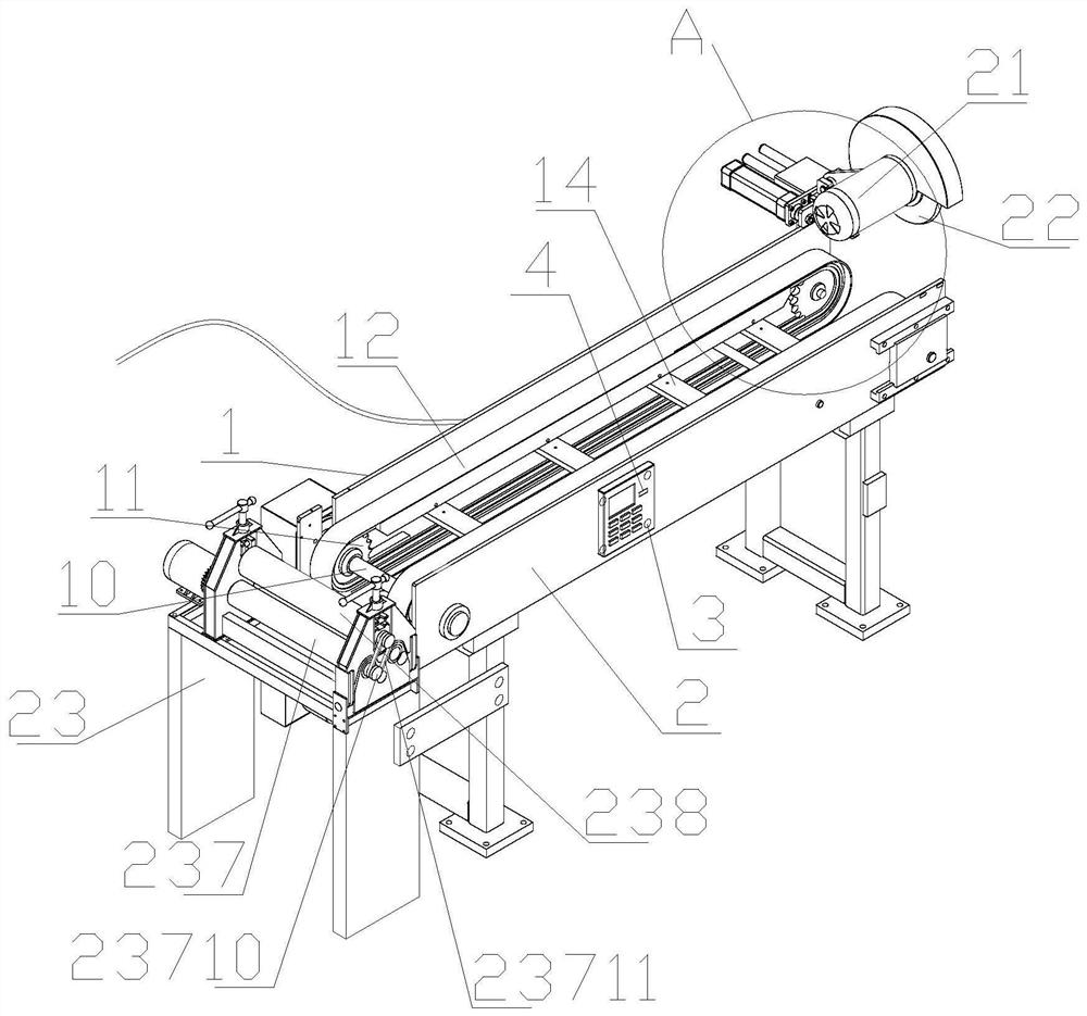
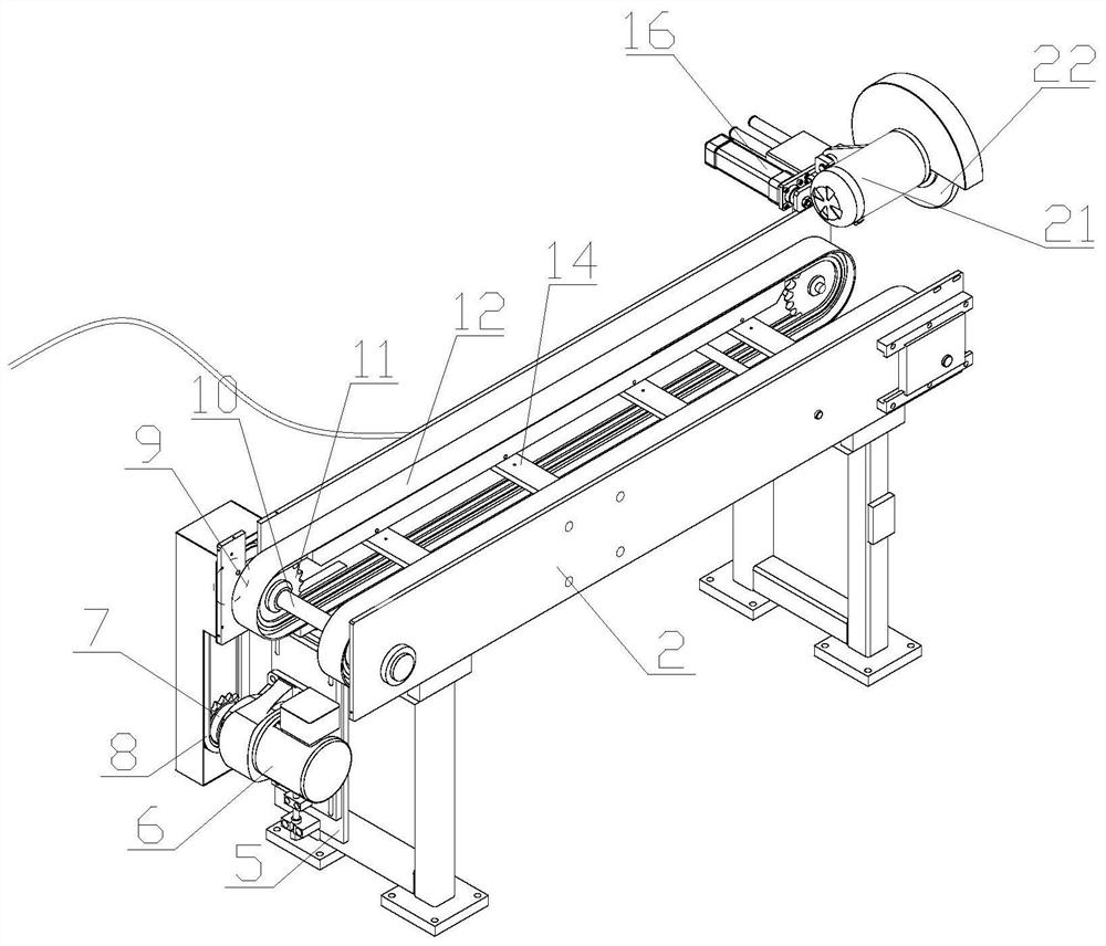
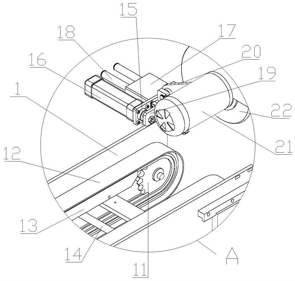
[0038] The following will be combined with Figure 1-7 The present invention is described in detail, and the technical solutions in the embodiments of the present invention are clearly and completely described. Apparently, the described embodiments are only some of the embodiments of the present invention, not all of them. Based on the embodiments of the present invention, all other embodiments obtained by persons of ordinary skill in the art without making creative efforts belong to the protection scope of the present invention.

[0039] The present invention provides a board cutting machine for aerospace through improvement, including a board cutting machine body 1, a fixed frame 2, a control panel 3, a controller 4, a connecting plate 5, a motor 6, a driving gear 7, a chain 8, and a slave Moving gear 9, transmission shaft 10, pulley 11, belt 12, fixed plate 13, connecting rod 14, fixed rod 15, cylinder 16, guide block 17, guide rod 18, second fixed plate 19, second connecti...


PUM


Abstract

The invention discloses a plate cutting machine for space flight and aviation. The plate cutting machine comprises a plate cutting machine body, a fixing frame, a control panel, a controller, a connecting plate, a motor, a driving gear, a belt wheel, a belt and a deburring device. According to the plate cutting machine, a third motor is started forwardly, a second transmission shaft is driven by acoupler to rotate, a third gear is driven by the second transmission shaft to rotate, the third gear rotates forwardly to drive a front gear and a rear gear to rotate at the same time, the rear gearrotates reversely, then the front gear and the rear gear drive a rotating shaft and a second rotating shaft at an inner diameter to rotate at the same time, the rotating shaft and the second rotatingshaft drive a sand roller and a second sand roller at an outer diameter to rotate at a high speed, a belt wheel assembly is inserted into the left end of the rotating shaft, an internal belt wheel ofthe belt wheel assembly is inserted into the rotating shaft and an internal rotating shaft of a third sand roller at the same time, the rotating shaft drives the belt wheel assembly to rotate at the inner diameter of a second belt, the belt wheel assembly is driven to drive the third sand roller to rotate forwardly, and the sand roller, the second sand roller and the third sand roller rotate to convey a profile board at the inner diameter at the right end and grind and debur the surface of the passing profile board.

Description

technical field [0001] The invention relates to the relevant field of cutting boards for aerospace, in particular to a board cutting machine for aerospace. Background technique [0002] Aerospace composite board is a high-performance new material board used in aerospace vehicles, which is compounded by two or more heterogeneous, special-shaped and heterogeneous materials through a special molding process. The purpose of the composite is to improve the performance of the material. Performance, while the aerospace composite board has high requirements on the smoothness of the material corners, and after the ordinary equipment is processed, manual secondary processing is time-consuming and laborious. In view of the above situation, it is necessary to provide a board cutting machine for aerospace. [0003] However, there are the following problems in the existing board cutting machine for aerospace: [0004] 1. Existing board cutting machines for aerospace use have high require...

Claims


Application Information

Patent Timeline
Patent Type & Authority Applications(China)
IPC IPC(8): B24B9/02B24B41/00B24B41/04B24B47/12B23D45/00B23Q3/06
CPCB23D45/003B23Q3/06B24B9/02B24B41/005B24B41/04B24B47/12
Inventor 罗火云
Owner 罗火云
Why Eureka
Try Eureka