
Spliced fluorescent pre-coated steel plate

A technology of pre-painted steel plates and fluorescent paints, applied to coatings, building components, layered products, etc., can solve the problems of difficult to distinguish the direction of the passage, damage at the edge, inconvenient construction, etc., to save installation and connection materials, The effect of reducing the cost of use and saving labor for installation

Pending Publication Date: 2021-03-30
江苏君安新材料科技有限公司
View PDF0 Cites 0 Cited by
  • Summary
  • Abstract
  • Description
  • Claims
  • Application Information

AI Technical Summary

Problems solved by technology

When the color steel plate is used for wall panels and wall panels of various enclosure structures, the visual effect of the flat and smooth color steel plate is monotonous, and the friction resistance is small when touched on the smooth surface, and the feeling lacks a sense of attachment and security. At night, especially where there is a lack of lighting, the smooth and flat color steel plate used as the side panel of the channel will make it difficult for people to distinguish the direction of the channel
When the color steel plate is used in the enclosure structure, the edge needs to be fixed with special screws, and there will naturally be gaps between the adjacent color steel plates, and the edges will be damaged during dismantling and it is difficult to reuse. , The occasion of short-term use is a waste, and the construction is inconvenient

Method used


Image

  • Spliced fluorescent pre-coated steel plate
  • Spliced fluorescent pre-coated steel plate
  • Spliced fluorescent pre-coated steel plate

Examples


Embodiment Construction

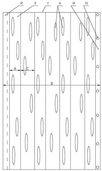
[0024] exist figure 1 and figure 2 In the spliced ​​fluorescent pre-coated steel plate shown, the steel plate body 1 is a rectangular carbon structural steel plate, and grooves 2 are arranged at intervals on the upper surface of the steel plate body 1, see image 3The longitudinal direction of the groove 2 is parallel to the longitudinal direction of the steel plate body 1 and the length of the groove 2 is equal to the length of the steel plate body 1, and the ratio A:B of the width A of the groove 2 to the width B of the steel plate body 1 can be taken as 1 :6~1:15, the ratio A:C of the width A of the groove 2 to the distance C between two adjacent grooves 2 can be taken as 0.8:1~1:1.2, see Figure 4 , the ratio E:G of the depth E of the groove 2 to the thickness G of the steel plate body 1 can be taken as 0.1:1~0.3:1; one side of the steel plate body 1 is provided with an overlapping bottom edge 14, and the side opposite to the side There is an overlapping top edge 12, an...


PUM


Abstract

The invention discloses a spliced fluorescent pre-coated steel plate which comprises a steel plate body made of carbon structural steel, grooves are formed in the upper surface of the steel plate bodyat intervals, a lap joint bottom edge and a lap joint top edge are arranged on the two opposite sides of the steel plate body respectively, the lap joint bottom edge can be inserted into the lower portion of the lap joint top edge, and a plurality of magnets are embedded into the lap joint bottom edge. A plurality of concave grains are arranged on the upper surface of the steel plate body and thebottom surfaces of the grooves, a passivation layer, a plating layer, a coupling layer, a color coating, a transparent film layer and a protective film layer are arranged on each surface of the upperside of the steel plate body from inside to outside, and noctilucent paint or fluorescent paint is loaded in concave parts, corresponding to the concave grains, in the color coating. A passivation layer, a plating layer, a coupling layer and a color coating are arranged on the lower surface of the steel plate body from inside to outside. By the adoption of the spliced fluorescent pre-coated steelplate, the defect that the spliced fluorescent pre-coated steel plate is too smooth when used as a wall and a channel enclosure can be overcome, the spliced fluorescent pre-coated steel plate has thefunction of lighting at night, adjacent corrugated color steel plates can be connected and detached conveniently, and the use cost is reduced.

Description

technical field [0001] The invention relates to a metal plate, in particular to an improvement of a color steel plate. Background technique [0002] As a kind of anti-corrosion, high-strength, paint-free and bright metal plate, color steel plate has been widely used in various industries, especially in the construction industry, it is widely used to make building roofs, walls and other components, and is also widely used in All kinds of enclosure structures, such as various types of wall panels, wall panels on both sides of the channel, etc. When the color steel plate is used for wall panels and wall panels of various enclosure structures, the visual effect of the flat and smooth color steel plate is monotonous, and the friction resistance is small when touched on the smooth surface, and the feeling lacks a sense of attachment and security. At night, especially where there is a lack of lighting, the smooth and flat color steel plate used as the side panel of the passage wil...

Claims


Application Information

Patent Timeline
Patent Type & Authority Applications(China)
IPC IPC(8): B32B3/30B32B15/04B32B15/085B32B15/18B32B27/06B32B27/32B32B1/06B32B1/00
CPCB32B3/30B32B15/04B32B15/18B32B15/085B32B27/06B32B27/32B32B2255/06B32B2255/28B32B2255/26B32B2307/422B32B2419/00B32B1/00
Inventor 陈钢顾国鼎
Owner 江苏君安新材料科技有限公司
Learn More