Enamel firing bracket used for firing enamel ornaments

An enamel and jewelry technology, applied in the field of jewelry processing tools, can solve the problems of uneven shapes and sizes, waste of financial resources and space, and many shapes and specifications, so as to increase the scope of application, simple and easy operation, and safer. Good results

Pending Publication Date: 2021-03-30
BEIJING INST OF CLOTHING TECH
View PDF0 Cites 0 Cited by
  • Summary
  • Abstract
  • Description
  • Claims
  • Application Information

AI Technical Summary

Problems solved by technology

[0004] 1. There are many shapes and specifications, and there are no standard parts: there are many shapes and sizes and specifications are uneven, and the brackets of each shape and specification are only suitable for fixing enamel pieces within a certain size range for firing, causing the operator to need to fix the enamel before firing. Reserve brackets with multiple specifications and different styles, resulting in a large waste of financial resources and space;
[0005] 2. Fixed size: the existing bracket can only be used to fire one enamel piece at the same time, and there are great limitations in shape and size. It is necessary to purchase brackets of various shapes and specifications
[0006] 3. Dangerousness: The firing tools for enamel pieces must be made of steel sheets resistant to high temperatures of about 1000°C. Most of them are long, pointed and welded and fixed. risk of injury

Method used


Image

  • Enamel firing bracket used for firing enamel ornaments
  • Enamel firing bracket used for firing enamel ornaments
  • Enamel firing bracket used for firing enamel ornaments

Examples


Embodiment Construction

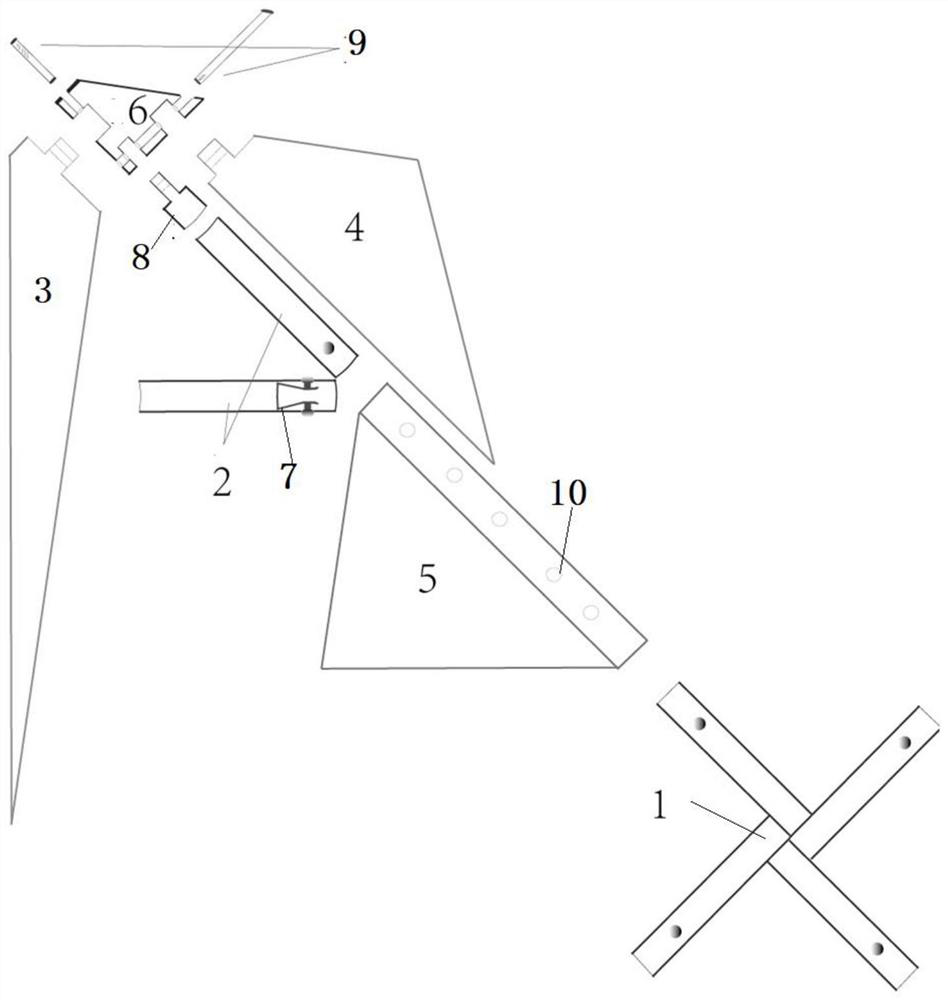
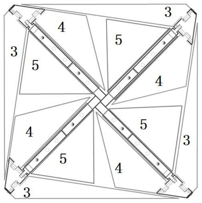
[0038] see Figure 1-3 , an enamel firing bracket for firing enamel ornaments in this embodiment, comprising: a central bracket 1, three layers of triangular brackets and angle irons 6, wherein the central bracket 1 forms a cross extending outward from the center The main shaft, the outer outline is square or rectangular, and the overall shape is square or rectangular; the triangular support is a structure that can be opened and closed, and can be flat or erected according to needs. The three-layer triangular support is fixed on the central support by folding. On the rack 1, the three-layer triangular support is an openable structure, which can be squared or erected according to needs. During use, the three-layer triangular support can be opened and closed according to needs, and folded into a plane after use, which saves space and does not have to be tied. Risk of injury; the angle iron 6 is used to connect the center bracket 1 and the three-layer triangular bracket, and the ...


PUM

PropertyMeasurementUnit
thicknessaaaaaaaaaa
thicknessaaaaaaaaaa
thicknessaaaaaaaaaa

Abstract

The invention provides an enamel firing bracket used for firing enamel ornaments. The enamel firing bracket used for firing the enamel ornaments comprises a central bracket, three layers of triangularsupporting pieces and angle iron, the central bracket forms a cross-shaped main shaft extending outwards from the center, the outer contour of the central bracket is square or rectangular, the wholeis square or rectangular, the triangular supporting pieces are of an openable and closable structure, can be horizontal or erected according to needs and are fixed to the center bracket in a layered mode in a folding mode, the three layers of triangular supporting pieces are opened and closed according to needs in use and folded into a plane after being used, the angle iron is used for connectingthe center bracket and the three layers of triangular supporting pieces, and the angle iron is connected with the cross-shaped main shaft formed by and the center bracket through nails in a hinge structure. The center bracket and extending brackets are steel brackets, the cross-shaped main shaft is a hollow steel pipe with an inner sleeve layer and an outer sleeve layer, elastic pieces are arranged in an inner pipe of the hollow steel pipe, and round holes are formed in corresponding positions of an outer pipe of the hollow steel pipe, so that the triangular supporting pieces are erected or extend.

Description

technical field [0001] The invention relates to the technical field of jewelry processing tools, in particular to an enamel firing bracket used for firing enamel ornaments. Background technique [0002] Enamel jewelry (especially enamel jewelry, clothing enamel decorations, small enamel ornaments, etc.) is more and more popular among contemporary people because of its colorful and "noble" quality. The inheritance of traditional crafts has also pushed enamel crafts to ordinary people. [0003] As an important carrying tool in the enamel firing process, the current problems and defects of the enamel bracket are as follows: [0004] 1. There are many shapes and specifications, and there are no standard parts: there are many shapes and sizes and specifications are uneven, and the brackets of each shape and specification are only suitable for fixing enamel pieces within a certain size range for firing, causing the operator to need to fix the enamel before firing. Reserve bracke...

Claims


Application Information

Patent Timeline
Patent Type & Authority Applications(China)
IPC IPC(8): C23D9/00
CPCC23D9/00
Inventor 刘静傅永和鲁硕张乐
Owner BEIJING INST OF CLOTHING TECH
Why Eureka
Try Eureka