Rainwater collecting device for building bridge and construction method thereof

A rainwater collection device and bridge technology, which is applied to watering devices, water supply devices, buildings, etc., can solve the problems of wasting rainwater resources, wasting manpower and material resources, and affecting aesthetics, and achieves the effect of saving manpower and material resources and removing dust.

Active Publication Date: 2021-03-30
鼎宏荣业建设集团有限公司
View PDF6 Cites 1 Cited by
  • Summary
  • Abstract
  • Description
  • Claims
  • Application Information

AI Technical Summary

Problems solved by technology

[0002] With the rapid growth of the national economy, the speed of urbanization in China is accelerating. In order to solve the pressure of urban traffic, bridges are erected on the main roads of many cities. Bridges are important traffic structures in cities to meet the needs of driving. The bridge deck It is difficult for the green belt below to receive rainwater irrigation directly; for the green belt that cannot receive irrigation, the commonly used method is artificial irrigation; and this method wastes both manpower and material resources, as well as rainwater resources. At the same time, during heavy rains, The direct discharge of rainwater into the sewer has also brought huge pressure to the urban sewage treatment system. The green plants under the bridge are seriously polluted by dust. Affected by the surrounding driving environment, the leaves of the plants under the bridge often adhere to a thick layer of dust , not only affects the appearance, but also the dust will block the pores on the leaves, so that the plants cannot absorb water and oxygen from the air or evaporate the excess water in the body to the outside, which reduces the life of the plants, and artificial watering cannot effectively remove the dust on the leaves

Method used


Image

  • Rainwater collecting device for building bridge and construction method thereof
  • Rainwater collecting device for building bridge and construction method thereof
  • Rainwater collecting device for building bridge and construction method thereof

Examples


Embodiment Construction

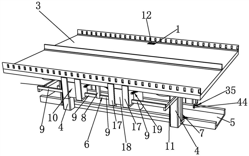
[0051] Such as Figure 1 to Figure 6 As shown, it is a kind of rainwater collection device used for building bridges of the present invention, comprising a rainwater outlet 1 and a drain outlet 2, the rainwater outlet 1 passes through the bridge deck 3, the drain outlet 2 is located at the bottom of the bridge pier 4, and the bottom of the bridge deck 3 is provided Green plant belt 5 is arranged, water outlet 2 supplies water for green plant belt 5, and the bottom of rainwater outlet 1 is fixedly connected with water delivery mechanism 6, and water delivery mechanism 6 is movably connected with drainage mechanism 7, and water outlet 2 is located at the bottom of drainage mechanism 7.

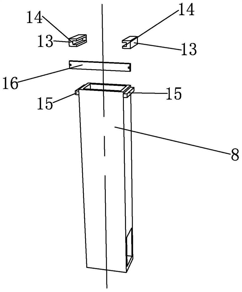
[0052] The water delivery mechanism 6 includes a water delivery main pipe 8, the top of the water delivery main pipe 8 is fixedly connected to the bottom surface of the rainwater outlet 1, and both sides of the bottom end of the water delivery main pipe 8 are connected with a first water delivery...


PUM


Abstract

The invention discloses a rainwater collecting device for a building bridge and a construction method thereof. The device comprises a rainwater opening and a water discharging opening, the rainwater opening penetrates through a bridge floor, the water discharging opening is located in the bottom of a bridge pier, a green plant belt is arranged below the bridge floor, the water discharging openingsupplies water to the green plant belt, and a water feeding mechanism is fixedly connected to the bottom of the rainwater opening, the water feeding mechanism is movably connected with a drainage mechanism, the water discharging opening is formed in the bottom of the drainage mechanism, and the method comprises the following steps of: a, preparation before construction; b, forming of the rainwateropening; c, pipeline mounting of the water feeding mechanism; d, mounting of the drainage mechanism; e, mounting of an adjusting assembly; f, mounting of a spray head; g, mounting of an overflow pipe; and h, circulating construction. Rainwater can irrigate and spray plants in a green plant belt under a bridge, manpower and material resources are saved, and certain help is provided for growth of the plants.

Description

technical field [0001] The invention belongs to the technical field of rainwater collection, and in particular relates to a rainwater collection device for building bridges and a construction method thereof. Background technique [0002] With the rapid growth of the national economy, the speed of urbanization in China is accelerating. In order to solve the pressure of urban traffic, bridges are erected on the main roads of many cities. Bridges are important traffic structures in cities to meet the needs of driving. The bridge deck It is difficult for the green belt below to receive rainwater irrigation directly; for the green belt that cannot receive irrigation, the commonly used method is artificial irrigation; and this method wastes manpower and material resources as well as rainwater resources. At the same time, during heavy rains, The direct discharge of rainwater into the sewer has also brought huge pressure to the urban sewage treatment system. The green plants under t...

Claims


Application Information

Patent Timeline
Patent Type & Authority Applications(China)
IPC IPC(8): E01D19/08E01D19/12B01D35/02A01G25/02E03F5/06
CPCE01D19/086E01D19/125B01D35/02A01G25/02E03F5/06
Inventor 金波
Owner 鼎宏荣业建设集团有限公司
Why Eureka
Try Eureka