Wind power generation device capable of adjusting blade windward area according to wind power

A technology of wind power generation device and wind receiving area, which is applied in the direction of wind energy power generation, wind turbine, and wind turbine combination, etc., can solve the problems of enlargement, relatively limited use conditions and generator damage, etc.

Active Publication Date: 2021-03-30
福建省晋江风电开发有限公司
View PDF6 Cites 0 Cited by
  • Summary
  • Abstract
  • Description
  • Claims
  • Application Information

AI Technical Summary

Problems solved by technology

[0002] Wind power generation is a device that drives the blades to rotate through the air flow, thereby driving the generator to rotate to achieve the conversion of wind energy into electrical energy. During the use of the device, the air flow velocity often increases and the speed of the blades increases accordingly. When encountering strong winds, measures are often taken to actively shut down the generator to prevent damage to the generator caused by excessive vibration frequency in the generator due to too fast blade speed, and this situation will also cause excessive power generation. The generator is damaged, and although this active avoidance method is effective, it will also make the use of conditions more restrictive.

Method used


Image

  • Wind power generation device capable of adjusting blade windward area according to wind power
  • Wind power generation device capable of adjusting blade windward area according to wind power
  • Wind power generation device capable of adjusting blade windward area according to wind power

Examples


Embodiment Construction

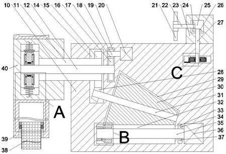
[0019] Combine below Figure 1-6 The present invention is described in detail, wherein, for the convenience of description, the orientations mentioned below are defined as follows: figure 1 The up, down, left, right, front and back directions of the projection relationship itself are the same.

[0020] combined with Figure 1-6 The wind power generation device for adjusting the wind-receiving area of ​​the blade according to the wind force includes a power generation box 10, and the upper end of the power generation box 10 is fixedly connected with a speed regulating device flush with the right end of the power generation box 10. The trigger box 23, the speed regulation trigger box 23 is provided with a speed regulation bevel gear cavity 25, the lower side of the power generation spur gear 15 is provided with a frequency modulation centrifugal cavity 67 located in the power generation box 10, the frequency modulation The left side of the centrifugal cavity 67 is communicated...


PUM


Abstract

The invention relates to the related field of wind energy, and discloses a wind power generation device capable of adjusting the blade windward area according to wind power. The wind power generationdevice comprises a power generation box body, wherein a speed regulation trigger box body flush with the right side tail end of the power generation box body is fixedly connected to the upper side tail end of the power generation box body, a speed regulation bevel gear cavity is formed in the speed regulation trigger box body, a frequency modulation centrifugal cavity located in the power generation box body is formed in the lower side of a power generation straight gear, and a frequency modulation push block cavity is formed in the left side of the frequency modulation centrifugal cavity in acommunicating mode. The change of the flow velocity of external airflow is detected through a speed regulation trigger fan wheel, and therefore the stressed area of a variable-force blade is changed,the rotating frequency of a power generation rotating block is reduced, and meanwhile, the purposes of ensuring running stability of the device and avoiding device disassembly caused by overhigh rotating speed of the power generation rotating block are achieved. The rotating speed of a power generation shaft is detected through a rotating speed sensor, the rotating frequency of a variable-speed electromagnet is changed, and therefore a generator is kept in the optimal power generation state and is also protected from being damaged by overhigh rotating speed of the power generation shaft.

Description

technical field [0001] The invention relates to the related field of wind energy, in particular to a wind power generating device which adjusts the wind-receiving area of ​​blades according to the wind force. Background technique [0002] Wind power generation is a device that drives the blades to rotate through the air flow, thereby driving the generator to rotate to achieve the conversion of wind energy into electrical energy. During the use of the device, the air flow velocity often increases and the speed of the blades increases accordingly. When encountering strong winds, measures are often taken to actively shut down the generator to prevent damage to the generator caused by excessive vibration frequency in the generator due to too fast blade speed, and this situation will also cause excessive power generation. The generator is damaged, and although this active avoidance method is effective, it also makes the use conditions more restrictive. Contents of the invention...

Claims


Application Information

Patent Timeline
Patent Type & Authority Applications(China)
IPC IPC(8): F03D9/25F03D7/02F03D15/00F16H33/06
CPCF03D9/25F03D7/022F03D7/0276F03D15/00F16H33/06F05B2270/32Y02E10/72
Inventor 李荣群
Owner 福建省晋江风电开发有限公司
Why Eureka
Try Eureka