
Incineration treatment equipment with cleaning function

A technology for processing equipment and functions, applied in lighting and heating equipment, incinerators, combustion methods, etc., can solve problems such as inability to automatically clean equipment, incomplete combustion of waste, and low incineration efficiency of incineration equipment

Inactive Publication Date: 2021-03-30
QUZHOU UNIV
View PDF0 Cites 2 Cited by
  • Summary
  • Abstract
  • Description
  • Claims
  • Application Information

AI Technical Summary

Problems solved by technology

During incineration, due to the accumulation of a large amount of waste, the burning flame will be extinguished due to the lack of oxygen due to the accumulation, and the waste cannot be completely burned, which affects the incineration effect, and after incineration, it is easy to stick some hard-to-clean coke on the side wall of the incineration treatment equipment Wait
Most of the existing incineration treatment equipment with cleaning function has the above-mentioned technical problems, that is, the incineration efficiency of the incineration equipment is low. In addition, the existing incineration equipment cannot automatically clean the equipment after the waste is incinerated

Method used


Image

  • Incineration treatment equipment with cleaning function
  • Incineration treatment equipment with cleaning function
  • Incineration treatment equipment with cleaning function

Examples


Embodiment Construction

[0044] Specific embodiments of the present invention will be described in detail below. It should be understood that the specific embodiments described here are only used to illustrate and explain the present invention, not to limit the present invention.

[0045] It should be noted that, in the present invention, the orientation words used such as "up, down, left, right, front, back" and figure 1 The up, down, left, right, front and back directions of the projection relationship itself are the same.

[0046] It should be noted that the terms "first" and "second" in the description and claims of the present invention and the above drawings are used to distinguish similar objects, but not necessarily used to describe a specific sequence or sequence. It should be understood that the data so used may be interchanged under appropriate circumstances for the embodiments of the invention described herein. Furthermore, the terms "comprising" and "having", as well as any variations t...


PUM


Abstract

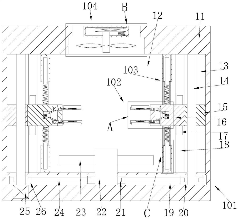
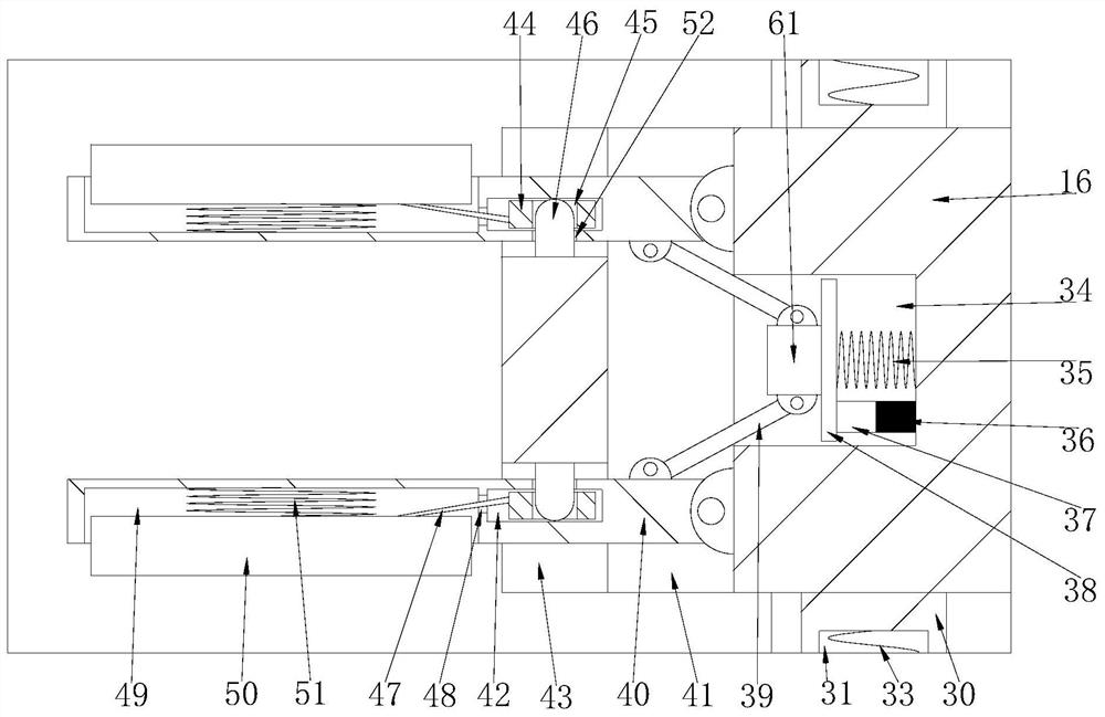
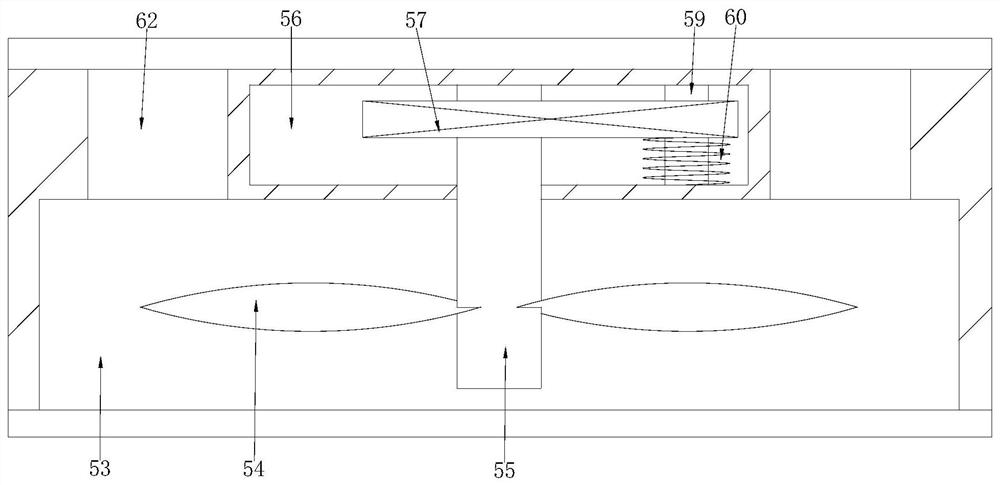
The invention relates to the technical field of incineration equipment, and discloses incineration treatment equipment with a cleaning function. The incineration treatment equipment comprises an incineration box, an incineration cavity is formed in the incineration box, symmetrical screw cavities are formed in the left wall and the right wall of the incineration cavity in a communicating mode, a belt cavity is formed in the lower side of the incineration cavity, the upper walls of the screw rod cavities are rotationally connected with main screw rods extending downwards to be rotationally connected with the lower wall of the belt cavity, the lower wall of the belt cavity is rotationally connected with a stirring shaft extending upwards into the incineration cavity, the outer circle face ofthe side, located in the incineration cavity, of the stirring shaft is fixedly connected with stirring blades, a power transmission mechanism is arranged in the belt cavity, and the outer circle faceof the main screw rod is in threaded connection with threaded connection blocks which are in vertical sliding connection with the side wall, away from the incineration cavity, of the screw rod cavities. According to the incineration treatment equipment, the rotation and the up-down movement of a shifting rod are driven by the transmission of a screw rod and a gear rack, and therefore, the waste can be shifted when being incinerated.

Description

technical field [0001] The invention relates to the technical field of incineration equipment, in particular to an incineration treatment equipment with cleaning function. Background technique [0002] In daily life, in addition to some household garbage, some wastes that are difficult to handle will also be produced. These wastes are generally disposed of by incineration. During incineration, due to the accumulation of a large amount of waste, the burning flame will be extinguished due to the lack of oxygen due to the accumulation, and the waste cannot be completely burned, which will affect the incineration effect, and after incineration, it is easy to stick some hard-to-clean coke on the side wall of the incineration treatment equipment Wait. Most of the existing incineration treatment equipment with cleaning function has the above-mentioned technical problems, that is, the incineration efficiency of the incineration equipment is low, and in addition, the existing incin...

Claims


Application Information

Patent Timeline
Patent Type & Authority Applications(China)
IPC IPC(8): F23G5/28F23G5/44
CPCF23G5/28F23G5/44F23G5/444
Inventor 贺庆韩沅伯覃克奎曹波二朱冬冬陈斌施艾晨王福云许柯银李范龙
Owner QUZHOU UNIV
Learn More