
Kitchen environment intelligent control system and control method

An intelligent control system and environment technology, applied in the field of kitchen environment, can solve problems such as not being able to improve installation efficiency, not being representative, and unfavorable for kitchen use, and achieve the effects of easy observation and recording, simple setting steps, and simple structure

Pending Publication Date: 2021-03-30
SHENZHEN XINCHUBANG TECH CO LTD
View PDF6 Cites 0 Cited by
  • Summary
  • Abstract
  • Description
  • Claims
  • Application Information

AI Technical Summary

Problems solved by technology

[0004] The object of the present invention is to provide a kitchen environment intelligent control system and control method to solve the problem that when monitoring the current kitchen environment proposed in the above-mentioned background technology, an integrated air detection device is used, and professional personnel are required for installation. The installation makes the installation steps complicated and cannot improve the installation efficiency. At the same time, it is not representative to conduct environmental detection in a single area, and the corresponding risk factor cannot be directly and efficiently detected, so that the danger cannot be dealt with in the first time. , resulting in serious follow-up development and the danger of being unable to be operated manually, which is not conducive to the use in the current kitchen, and is not intelligent at the same time. In today's society, it cannot meet the needs and is eliminated.

Method used


Image

  • Kitchen environment intelligent control system and control method
  • Kitchen environment intelligent control system and control method
  • Kitchen environment intelligent control system and control method

Examples


Embodiment Construction

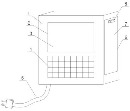
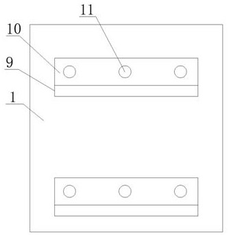
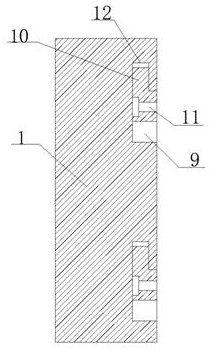
[0030] see Figure 1-3 , in the embodiment of the present invention, the kitchen environment intelligent control system and control method include a main outer casing 1, a socket groove 2 is opened on one side of the main outer casing 1, and a display screen is clamped on the inner side of the socket groove 2 3. The main housing body 1 is provided with a setting key 4 on the same side of the socket groove 2, and the side of the main housing body 1 is plugged with a power cord 5, and the socket groove 2 is opened on one side of the main housing body 1 The side is close to the position of the top surface, and one side of the display screen 3 is fixedly clamped and arranged on the side of the main controller 20, and the display screen 3 is electrically connected to the inside of the main controller 20. One end of the power cord 5 A plug is provided, and the other end extends through the outer side of the main outer casing 1 to the inside, and the extension end is electrically con...


PUM


Abstract

The invention discloses a kitchen environment intelligent control system and a control method, which relate to the field of kitchen environments. The kitchen environment intelligent control system comprises a main outer shell, one side edge of the main outer shell is provided with a sleeving groove, the inner side edge of the sleeving groove is clamped with a display screen, and the main outer shell is provided with a setting key on the same side edge of the sleeving groove; a power line is inserted into the side edge of the main outer shell, storage notches are symmetrically formed in the twoside edges of the main outer shell, a sealing rolling door is clamped to the inner side edges of the storage notches, a stirring block is horizontally welded to one side edge of the sealing rolling door, and a rear clamping groove is horizontally formed in the side edge, away from the sleeving groove, of the main outer shell. And a fixed transverse plate is horizontally clamped on the inner sideedge of the rear clamping groove. The device is designed to be of a split structure and is simple in structure, installation is easy and convenient by adopting a buckle and adsorption installation mode, meanwhile, wireless design enables the device to be simpler and more efficient, the multi-area monitoring effect enables the kitchen environment to be monitored in an all-around mode, and the device is safer and more reliable.

Description

technical field [0001] The invention relates to the technical field of kitchen environment, in particular to an intelligent kitchen environment control system and control method. Background technique [0002] A kitchen is a room in which food is prepared and cooked. A modern kitchen usually includes a stove (gas stove, electric stove, microwave or oven), and a counter (sink or dishwasher). and food storage equipment (eg refrigerators, freezers). Looking at the evolution of the kitchen pattern in Chinese history, it depends on the development of productivity on the one hand, and on the other hand, it also depends on the local natural conditions and the living habits of residents. Through the evolution of different periods, the functionality of the kitchen has gradually become more reasonable. [0003] When monitoring the current kitchen environment, an integrated air detection device is used. Professional personnel are required to install it during installation, which makes...

Claims


Application Information

Patent Timeline
Patent Type & Authority Applications(China)
IPC IPC(8): G01N33/00G08C17/02
CPCG01N33/0063G01N33/0073G01N33/0009G08C17/02
Inventor 桂诗勇
Owner SHENZHEN XINCHUBANG TECH CO LTD
Learn More